
PHILIPS EQUIPMENT for picture projection and sound reproduction of TODD—A.O. 70mm. FILM |
Read more at in70mm.com The 70mm Newsletter | ||||||||||||||||||||||||||||
| Written by: W. J. M. Jansen*, Philips Ltd., Eindhoven, Holland. Chairman: N. V. Leevers, B.Sc. (Fellow). Read to a meeting of the Society on January 30, 1957. * Philips Ltd., Eindhoven, Holland. Prepared for in70mm.com by Anders M. Olsson, Lund, Sweden | Date: 01.01.2013 | ||||||||||||||||||||||||||||
 Figure
1 Figure
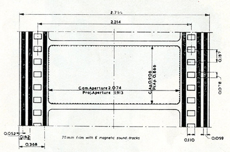
1The purpose of this paper is not to explain the Todd-A.O. system itself but the design of the Philips projector for this system. It is, however, necessary first to say a few words about those characteristics which have affected the design. The Todd-A.O. system employs a 70mm. film with a picture area of about 2.074 ins. x 0.906 ins. (Fig. 1). It is provided with six magnetic sound tracks. Standard perforations are used; the distance between the two rows of perforations is 2.104 ins. The frames are central with respect to the edges of the film. The centre distance of two consecutive frames is five times the perforation pitch. At each side there are three sound tracks, two outside and one inside the perforations. All the tracks have a width of 0.059 ins. The speed of the film is 30 frames/sec. Taking into account the greater height of the frames, this means that the film speed is about 50% higher than that of 35mm. films, viz. 140 ft. instead of 90 ft. per minute. It will be obvious that for the projection of a film twice as wide as normal film and running at such a high speed, the projector must satisfy special demands. Therefore the modification of a normal 35mm. projector— although possible for laboratory purposes— is not acceptable for practical use in cinema theatres. The projector must also be suitable for showing 35mm. films, because it can hardly be expected that a complete 70mm. programme will continuously be available on the market. Change-over from 35mm. to 70mm. projection, and vice versa, should only take a few minutes to allow of both types of film being shown in the same performance. |
More in 70mm reading: DP70 / Universal 70-35 / Norelco AAII - The Todd-AO Projector in70mm.com Presents: You are in the Show with Todd-AO Internet link: BRITISH KINEMATOGRAPHY VOLUME 30 No. 3 HON. EDITOR: R. J. T. BROWN (Fellow) HON. TECHNICAL EDITOR: W. S. BLAND (Fellow) MARCH, 1957 | ||||||||||||||||||||||||||||
The Projector—General Layout | |||||||||||||||||||||||||||||
 Figure
2 Figure
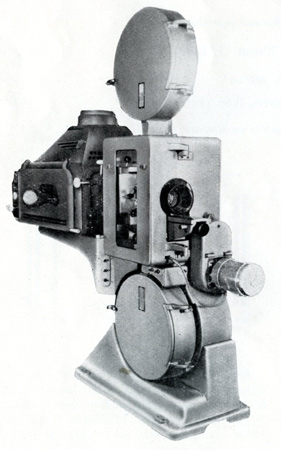
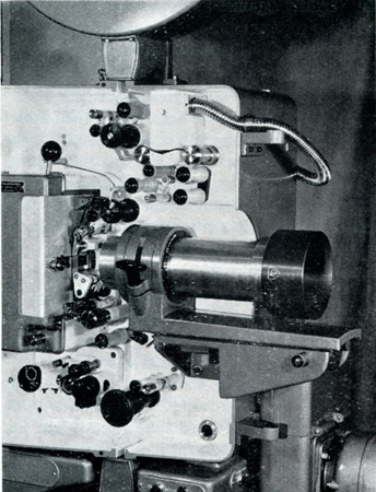
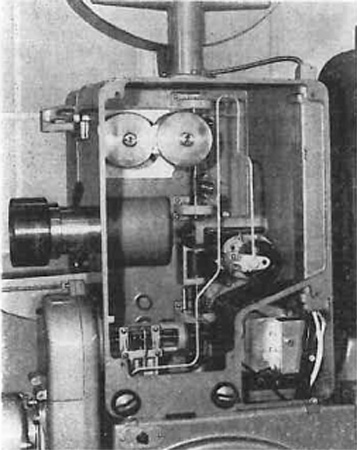
2Before discussing the construction in detail, a general idea of the projector will be given. Fig. 2 shows the projector with pedestal, mounting table, spool boxes and Peerless Hy-Candescent arc lamp. The pedestal consist of a “lower base” and an “upper base.” During the adjustment of the tilting angle the upper base rotates in the lower base round the shaft of the lower spool box. The driving motor is at the front of the projector. The push-buttons on the right are for starting, stopping and change-over and the three in a vertical row for switching on the arc lamp at half intensity, switching to full intensity and for switching it off. Fig. 3 shows the projector head with door removed to give a better view of the film path. In the right-hand top corner under the white box cover is the magnetic sound head for six-channel Todd-A.O. films and for four-channel CinemaScope films; the sound head for films with optical sound tracks is at lower left. |
|||||||||||||||||||||||||||||
Interchange from 70mm. to 35mm. | |||||||||||||||||||||||||||||
 Figure
3 Figure
3Let us now see which parts can be used for both 70mm. and 35mm. films and which parts have to be replaced. All the sprockets are provided with two sets of teeth; the outer set is spaced for 70mm. film and the inner set for 35mm. film. The number of teeth of the outer set is 1¼ times that of the inner set because 70mm. films have five perforations per frame and 35mm. films have four. Thus the intermittent sprocket has outer flanges with twenty teeth and inner flanges with sixteen teeth; for the other sprockets these numbers are thirty and twenty-four. The rollers of the fire trap and the guide rollers are double profiled and are, therefore, suitable for both 70 and 35mm. This applies also to the two rotating sound drums of the magnetic sound head and to the magnetic cluster. Consequently, neither of these parts need be replaced. The parts which have to be replaced are: the runner plate, some rollers, the pressure strips, the aperture plate and the lens. To reduce the number of manipulations for replacement to a minimum, the pad roller for the intermediate feed sprocket and that for the intermittent sprocket are fixed to the runner plate and are therefore automatically removed with this plate. Moreover, the runner plate comprises a film stripper for the intermittent sprocket and the outer bearing of the intermittent shaft. The whole unit is fixed by only one bolt which is fastened by hand, no tools being necessary. Only the pad roller of the upper feed sprocket and that of the hold-back sprocket, the pressure strips, the aperture plate and the lens have to be replaced separately. The pressure strips have the same function as the well-known pressure skates in normal projectors. All the pad rollers are pre-set and centred on guide pins. They are made of nylon, so that there is no risk of the sprocket teeth being damaged. The pressure roller on the first sound drum of the magnetic sound head need be replaced only for changing over from 70mm. films to 35mm. films with magnetic tracks and vice versa. The complete modification takes less than five minutes. |
|||||||||||||||||||||||||||||
Engineering Design Details | |||||||||||||||||||||||||||||
 Figure
4 Figure
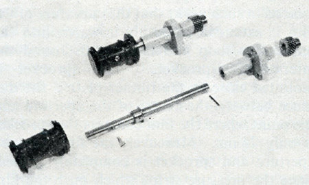
4Fig. 4 shows some of the projector parts. The sprockets with double sets of teeth are made of aluminium and by means of a special anodizing process they are coated with an oxide layer of about 60 microns in thickness. Life tests have proved that the life of these sprockets is at least equal to that of sprockets made of high-alloy steel. Apart from the low weight—which is especially important for the intermittent sprocket—aluminium has the advantage that it is anti-magnetic. All the parts of the projector which come into contact with the magnetic coating on the film are made of anti-magnetic material. Fig. 5 shows the runner plate with the two pad rollers. It is curved in a longitudinal direction, so as to obtain a greater stiffness of the film in the gate. The shape has been determined after extensive experiments under normal working conditions. The radius of the gate within the confines of the aperture is nearly 21 ins.; at this place the admissible curvature is determined by the depth of focus of the projection lens. Towards the top and the bottom the curvature increases gradually. The two running surfaces are ground on one precision casting of “Tantung,” an alloy of principally tungsten, chromium and tantalum carbide. Extensive tests have proved that it is essentially suitable as a material for the runner plate because of its great resistance against wear; moreover, it is anti-magnetic and non-corrosive. The runners have been made as wide as possible; in other words, they support the whole available width between the picture frames and the outer edges of the film. Tor Todd-A.O. film, this width is 0.35 ins. |
|||||||||||||||||||||||||||||
The Film Path | |||||||||||||||||||||||||||||
 Figure
5 Figure
5All the other parts of the film path have likewise been designed to give the maximum support to the film, i.e., to obtain maximum steadiness of the picture. The sprockets are located in such a way that the curvature of the film is extended smoothly upwards into the upper film loop and downwards round the intermittent sprocket. This sprocket is mounted close to the runner plate; the distance between the centre of the aperture and the point where the film contacts the sprocket is only 2⅜ ins. Moreover, the film between aperture and sprocket is completely guided, since the pressure strips which push the film against the runner plate have been extended past the intermittent sprocket and push the film slightly against this sprocket. Thanks to all these measures, absolute steadiness of the film between aperture and sprocket is obtained. In a lateral direction the film is guided by two rollers located at the top of the runner plate. One of these rollers is fixed, whilst the other, which is spring-loaded, pushes against the edge of the film. These rollers are interchangeable, which is of great advantage since, because of the tolerances in the dimensions of the various parts, the film often tends to run slightly to one specific side. The lateral guide rollers are mounted so that the spring-loaded roller supports the natural tendency of the film; the pressure of the spring—and hence also the force exercized on the film—is therefore kept as low as possible. The location of the lateral guide rollers just at the top of the runner plate, i.e. at a place where the film is not yet enclosed, is also based on the principle of minimizing the guiding forces. The following figures demonstrate the steadiness of the film. Measurements performed on over fifty projectors have shown that the vertical jump does not exceed 0.15% and that the weave does not exceed 0.2%. These values are considerably better than established standards. The two pressure strips, clearly seen in Fig. 6, are made of stainless steel with a thickness of 7.85 mils; each strip is suspended between two pivot points. The strips are slightly pre-curved in accordance with the curvature of the runner plate. They are so slack that, when the film path is closed, they follow this curvature truly and thus apply the required pressure. For this purpose the lower pivot points are resilient. An adjustable central spring guarantees equal tension of both strips. |
|||||||||||||||||||||||||||||
Cooling and Safety Device | |||||||||||||||||||||||||||||
|
The pressure strips are mounted on a
vertical copper plate, the cooling plate, which also carries a simple
clamping device for the various aperture inserts. At the rear of this
plate, the aperture is encircled by a pipe through which the cooling
water flows. The aperture inserts are made of heat-conducting copper-alloy; pure copper is too soft for this purpose. They are electrolytically silver-plated and ensure good heat dissipation round the aperture. During operation, the temperature of the inserts themselves does not exceed 95°F. (35°C.), provided that the water flow is sufficient. For safety reasons, a microswitch inserted in the water-supply system switches off the arc lamp automatically as soon as the water pressure becomes too low. The cooling plate is mounted in a hinged holder. The pivot point lies below the intermittent sprocket. When the holder is turned backwards the pressure strips are lifted from the runner plate and the film can be threaded. The pivot point of the holder has been so chosen that, when the holder is closed again, the film is immobilized first between the pressure strips and the intermittent sprocket and then gradually further upwards. Consequently, the film is stretched over the runner plate from the bottom upwards and the upper film loop is formed automatically. When the gate is opened for threading the film, the runner plate is not moved; the lens, therefore, need not be shifted and will not become out of focus. To make pivoting of the copper cooling plate possible, a single-blade shutter is used. The cooling plate can pass freely when the blade is in the position farthest away from the light beam; in this position of the shutter the shaft of the intermittent sprocket is locked by the cam shaft, which is a condition for accurate threading of the film. Before the film gate is opened, the projector has to be inched to this position, which is clearly indicated by radial lines on the intermediate feed sprocket. A safety device on the shutter shaft keeps the film gate locked as long as this condition has not been fulfilled. When the gate is open, a microswitch interrupts the motor circuit. Close behind the gate aperture is a light cut-off which is opened by an electromagnet which closes by its own weight as soon as the energizing circuit of the magnet is interrupted. The cut-off is used for change-over from one projector to the other and for safety reasons; thus, for example, it is closed automatically as soon as the speed of the projector drops below about 16 frames/sec, and also when the motor is switched off. Another safety device switches off the motor when the upper film loop becomes too large. |
|||||||||||||||||||||||||||||
Lens Holder | |||||||||||||||||||||||||||||
 Figure
6 Figure
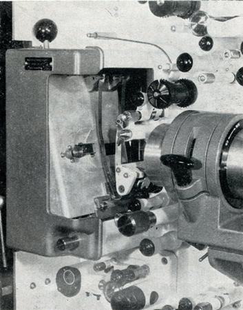
6Referring to Fig. 3 it will be seen that the lens holder is remarkable for its very long and sturdy support, necessitated by the size and weight of the lenses required. The focusing device is simple: a heavy spring pushes a stud at the bottom of the lens holder against the knurled focusing screw. This construction guarantees fine adjustment without backlash. The tension of the spring can be adjusted between wide limits, in accordance with the tilting angle of the projector. Because of the spring load, different forces have to be exercized for shifting the lens holder one way or the other, but this difference is minimized by the fine thread (28 per inch) in conjunction with the large diameter (½ in.) of the focusing screw. The lens holder can be removed by slightly compressing the spring and locking it. |
|||||||||||||||||||||||||||||
Sound heads | |||||||||||||||||||||||||||||
 Figure
7 Figure
7The sound heads, although built in, form separate units. The magnetic sound head has two sound drums, running in precision ball-bearings and provided with heavy flywheels. The magnetic cluster is located between these sound drums which are provided with flanges of anti-magnetic chromium-steel between which the film is guided in a lateral direction. A spring-loaded roller pushes the film on to the first sound drum. The required tension in the piece of film between the two feed sprockets is obtained by means of a second spring-loaded roller. With the exception of the pressure roller, all the rollers and the two sound drums are so profiled as to be suitable for both 35mm. and 70mm. films. For the 35/70mm. conversion, only the pressure roller need be substituted. The magnetic cluster (Fig. 7) is equipped with ten cores, viz. six for Todd-A.O. and four for CinemaScope films. The entire cluster is enclosed in a mu-metal shield. The response curve is flat within ± 2 dB up to a frequency of 12,000 c/s. |
|||||||||||||||||||||||||||||
 Figure
8 Figure
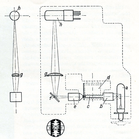
8The optical sound head is used only for 35mm. films. The contact between film and sound drum is likewise ensured by a spring-loaded pressure roller provided with flanges. The spindle of this roller is at a small angle with the sound drum, so that the film edge is always guided by the front flange. This sound head does not incorporate special damping rollers; the intermittence in the speed of the film is filtered out by two rollers on the projector itself, located directly after the lower film loop. Irregularities introduced by the hold-back sprocket are completely filtered out by the slack film between sound drum and hold-back sprocket. In this sound head, an enlarged picture of the sound track is projected by a microlens on to a screen, provided with a slit (Fig. 8). The position of the sound track with respect to the slit can be adjusted by means of a knurled knob and checked through an observation window. The film is pulled through the optical sound head by the hold-back sprocket. |
|||||||||||||||||||||||||||||
Driving Mechanism | |||||||||||||||||||||||||||||
 Fig
9 Fig
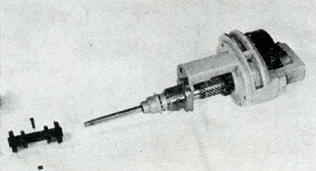
9A split-phase asynchronous motor drives the mechanism via a V-belt. The motor shaft is provided with two fixed V-pulleys, and the horizontal main shaft with two pulleys, either of which can be coupled to the shaft by means of a friction clutch. This construction constitutes a safe and simple method of changing the film speed from 30 to 24 frames/sec, and vice versa. Figure 9 shows a view of the projector with the rear cover plate removed. The horizontal shaft drives the vertical main shaft and the high-pressure oil pump. This is a spur-gear pump which is always below the oil level, even at very steep projection angles. The oil is forced via an oil pipe system to all the gear-wheel transmissions and bearings; finally it enters the housing of the intermittent unit. The overflow of this housing is located behind the window in the rear cover of the projector, thus permitting instantaneous checking of the working of the lubricating system. The oil pump is provided with a double filter, viz. a gauze filter followed by a magnetic filter, both accessible from the outside. Two further magnetic filters are mounted in the housing of the intermittent unit. All the sprockets as well as the shutter are driven by direct gearing from the central, slow-running main shaft. This shaft is extended downwards as a separate shaft which passes through the bottom of the projector and drives the take-up spool. The main shaft runs in three ball-bearings. At 30 frames/sec its speed is 450 r.p.m. The gears for driving the feed sprockets and the hold-back sprocket are milled directly on this shaft, which reduces the number of separate gear wheels to an absolute minimum. With the exception of the transmissions to the slowly running sprocket spindles, one of the gear wheels of each transmission is made of high quality Novotex. It will be obvious that all these factors favour a smooth and silent running projector. Let us consider the various elements in the sequence in which they are coupled to the main shaft, from top to bottom. Right at the top is the first feed sprocket which pulls the film from the supply reel and underneath there is a second feed sprocket for pulling the film through the magnetic sound head. As the sound head is mounted in the projector, these two functions can be separated, which gives some important advantages over the usual “penthouse” sound head—where the take-off sprocket is not coupled to the mechanism but is driven by the film—viz. lower stress on the film perforations and smoother running of the film through the sound head, since irregularities originating from the unwinding reel are completely excluded. Moreover, the stress on the film perforations is reduced by the large diameter of the feed sprockets and hence the large number of teeth engaged in the perforations. The sprocket spindles run in cast-iron plain bearings and are provided with oil throwers which return the oil after it has passed the bearings. |
|||||||||||||||||||||||||||||
The Shutter | |||||||||||||||||||||||||||||
|
The shutter has been designed with a view
to obtaining maximum light efficiency. The basic means to achieve this
goal are, of course, high velocity of the shutter and its location close
to the picture gate. The first condition has been fulfilled by using a
single-blade shutter with a large diameter, viz. nearly 12 ins., running
at two revolutions per projection period. The angle of the shutter blade
is 170°, the distance between shutter and picture gate is less than ½
in. The calculated light efficiency obtained with this shutter is 53 per
cent. It will be obvious that the high speed (3,600 r.p.m.) and the large dimensions of the shutter impose severe demands on the construction of the driving mechanism, the bearings and the equilibrium of the system. The shutter is driven directly from the main shaft by means of helical gears with a transmission ratio of 1:8. The shutter shaft runs in two ball-bearings mounted in a sturdy bracket; the front bearing is of the double-row, pre-loaded type. The facility of adjusting the shutter from outside—which is usual for American type projectors—has been abandoned on the consideration that basically the position of the shutter has to be adjusted once and for all, and will then be definitely correct. Subsequent re-adjustment by the projectionist can never improve, but only impair the situation. The construction, of course, should be such that the correct position is definitely maintained. A device for adjusting the shutter during operation inevitably implies a complication of its driving mechanism which, owing to the great stress on this mechanism, is undesirable. |
|||||||||||||||||||||||||||||
The Intermittent Mechanism | |||||||||||||||||||||||||||||
 Figure
10 Figure
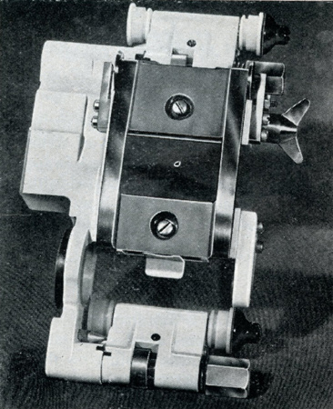
10The intermittent mechanism is based on the four segment Maltese cross. To ensure maximum steadiness of the picture in spite of the fact that the sprocket shaft protrudes over a rather great length (Fig. 10), the end of the shaft is supported by an additional bearing. It was not possible for this bearing to be held by a bracket mounted on to the frame of the intermittent unit, since the bracket would then seriously mar the accessibility of the sprocket. The bearing has therefore been mounted in the gate assembly. This has made it necessary to keep the position of the sprocket shaft with respect to the gate assembly within very close tolerances, as otherwise the bearing would have to be re-adjusted whenever the gate assembly or the intermittent unit were replaced. This signifies not only that all parts involved had to be made and assembled with the utmost precision, but it also fixes exactly the centre distance between the cam shaft and the shaft of the Maltese cross. It was therefore impossible to mount, as usual, the cross shaft in an eccentric bushing for adjusting the play between the faces of cam and cross. In this projector cam and cross have been made conical instead of cylindrical, so that the correct play between these two faces can be obtained by shifting the cam shaft in an axial sense. For the rest, the construction of the intermittent mechanism does not differ from normal Philips practice. With the exception of the gear wheels and the intermittent sprocket, all the moving parts are made of alloy steel, hardened and ground. Two magnetic filters are fitted in the oil bath of the intermittent unit. The sprocket is of anodized aluminium; in spite of its large dimensions, its weight is less than one ounce. Framing is effected by rotating the complete intermittent mechanism round the shaft of the Maltese cross; for this purpose, the frame carries a toothed segment. |
|||||||||||||||||||||||||||||
Amplifier Equipment | |||||||||||||||||||||||||||||
|
A special amplifier assembly has been
designed for the reproduction of six-channel magnetic sound. It is truly
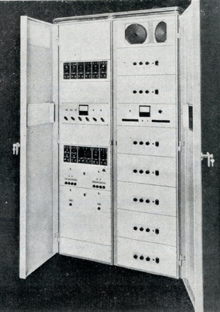
“all purpose,” since it is suitable for the reproduction of: (a) six-track Todd-A.O. magnetic sound; (b) four-track magnetic sound; (c) single-track magnetic sound; (d) single-track optical sound. Moreover, the cabinet has space and terminals for a Perspecta-Sound integrator. The complete equipment is built in twin 19 in. racks (Fig. 11). The right-hand part contains the power amplifiers with monitoring facilities and the left-hand part all the preamplifiers, power-supply units and further auxiliary equipment. There are no direct connections between the left-hand and the right-hand rack. All the outgoing leads of the pre-amplifiers go to the combined system-selector and volume-control box and from there to the input terminals of the power rack. |
|||||||||||||||||||||||||||||
 Figure
11 Figure
11The left-hand rack contains from top to bottom: (a) A blind panel which can be substituted by a panel with Perspecta-Sound integrator; the supply unit for the integrator is then inserted instead of the blind panel at the bottom. (b) A panel with six magnetic preamplifiers of the plug-in type, any one of which can, in the event of a breakdown, easily be replaced by the spare unit. Each pre-amplifier has a gain control, a treble filter for equalizing, and three push-buttons for checking the valves; when a valve is correct, the needle of the meter deflects to the centre of the scale when the relevant button is depressed. (c) Two blind panels, one above and one below the master control panel; behind these panels are all the terminals for the incoming and outgoing cables and for the system-selector and change-over relays. (d) The master control panel, which will be referred to later on. (e) A panel with two pre-amplifiers for optical sound reproduction, one non-sync. pre-amplifier, the 12 kc. unit for the fourth track of CinemaScope films and a spare magnetic pre-amplifier which is always pre-heated. All these units are of the plug-in type. The two optical pre-amplifiers are identical; one is in operation and the other serves for stand-by. They are provided with photocell voltage-controls for equalizing the outputs of up to three optical sound heads, a treble-correction filter and a gain control. The non-sync. pre-amplifier is equipped with gain controls for four different signal sources, for example, a magnetic recorder, a microphone, a pick-up, etc. (f) A panel with two identical feed units, each of which can supply all the anode and heating currents necessary for all the pre-amplifiers as well as the direct current for the picture change-over and system-selection relays. For each supply unit there are a pilot lamp which lights up as soon as the relevant unit is selected by a switch on the master control panel, two pushbuttons for testing the anode and relay voltages, and four fuses. (g) A panel with a rectifier for D.C. supply of the exciter lamp and, as a spare, a separate transformer for emergency A.C. supply. Two pilot lamps indicate whether A.C. or D.C. is supplied. |
|||||||||||||||||||||||||||||
|
The master control panel is equipped with
the following controls: Upper row: (i) the selector switch for choosing either of the two optical pre-amplifiers; (ii) a bass cut-off switch for prints with boomy optical sound track; (iii) a treble cut-off switch for prints with optical tracks with a too high hiss level; (iv) the measuring instrument for testing the valves; (v) the pilot lamps for change-over. |
|||||||||||||||||||||||||||||
|
Lower row: (i) three selector switches for choosing the two projectors to operate in projection rooms equipped with three projectors; (ii) the selector switch for feeding the exciter lamp with D.C. or A.C.; (iii) a switch for switching off the exciter lamp supply when the programme contains only prints with magnetic sound tracks; (iv) the selector switch for choosing either of the two power-supply units for the pre-amplifiers. The right-hand rack contains seven identical power amplifiers, each with an output of 30 W, viz., 20 W for the auditorium and 10 W for the monitor loudspeakers mounted at the top. Six amplifiers are needed for the six Todd-A.O. sound tracks and the seventh serves as a standby. |
|||||||||||||||||||||||||||||
|
The control panel of each power amplifier
is provided with: (i) a volume control; (ii) a bass filter; (iii) a treble filter; (iv) a pilot lamp and (v) a mains switch. |
|||||||||||||||||||||||||||||
 Figure
12 Figure
12On the master control panel are located: (i) an output meter, connected in parallel to the monitor loudspeakers; (ii) the master mains switch for the complete amplifier assembly and a pilot lamp which lights up when the normal six channels are operating; (iii) the volume control for the monitor loudspeakers; (iv) seven push-buttons, six for selecting the channel to be monitored and the seventh for switching off the monitor loudspeakers; (v) seven push-buttons of which normally only the seventh is depressed; in the event of a breakdown in either of the normal six power amplifiers, the corresponding button is depressed and this amplifier is automatically replaced by the seventh, the spare amplifier; a pilot lamp lights up when the stand-by amplifier is used. |
|||||||||||||||||||||||||||||
 All the connections of the power rack and
the six cross-over networks are behind the side door at the right. All the connections of the power rack and
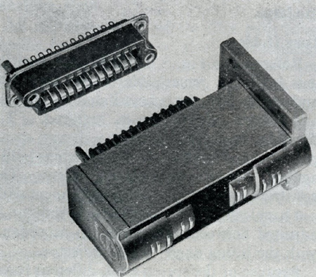
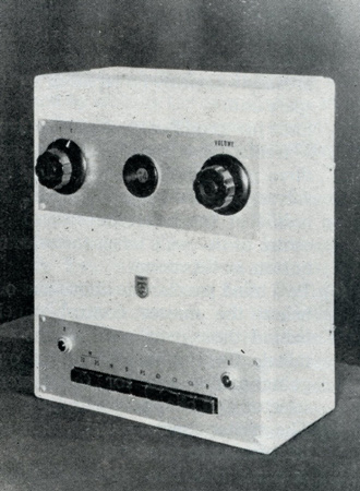
the six cross-over networks are behind the side door at the right.The system-selector and volume-control box (Fig. 12) contains a six-channel volume control. As it was impossible to mount the six potentiometers on one shaft, they are coupled to the operating knob by means of a gear-wheel transmission. The dial is visible behind the illuminated window in the centre. At the left is a switch for change-over to a remote volume control. There are nine push-buttons for system selection. First a button is depressed to choose either magnetic or optical sound reproduction. When magnetic sound is chosen, then either the button for Todd-A.O. or for CinemaScope is depressed. When optical sound is chosen, the Perspecta-Sound button can be depressed subsequently, when desired. The four other buttons serve for sound sources other than film. Two pilot lamps indicate whether the left-hand or the right-hand projector is connected to the amplifier assembly. |
|||||||||||||||||||||||||||||
The following figures give some technical data of the amplifier equipment | |||||||||||||||||||||||||||||
|
|||||||||||||||||||||||||||||
|
Go: back - top - back issues - news index Updated 21-01-24 |