|

“Almost like a real web
site”
|
IN7OMM.COM
• Search |
Contact
• News |
e-News |
• Rumour Mill |
Stories
• Foreign Language
• in70mm.com auf Deutsch
WHAT'S ON IN 7OMM?
7OMM FESTIVAL
• Todd-AO Festival
• KRRR! 7OMM Seminar
• GIFF 70, Gentofte
• Oslo 7OMM Festival
• Widescreen Weekend
TODD-AO
• Premiere |
Films
• People |
Equipment
• Library |
Cinemas
• Todd-AO Projector
• Distortion Correcting
PANAVISION
• Ultra Panavision
70
• Super Panavision
70
|
 |
|
VISION, SCOPE & RAMA
1926
Natural Vision
1929 Grandeur
1930 Magnifilm
1930 Realife
1930 Vitascope
1952 Cinerama
1953
CinemaScope
1955 Todd-AO
1955 Circle Vision
360
1956
CinemaScope 55
1957 Ultra
Panavision 70
1958 Cinemiracle
1958 Kinopanorama
1959 Super
Panavision 70
1959 Super Technirama 70
1960 Smell-O-Vision
1961 Sovscope
70
1962
Cinerama 360
1962 MCS-70
1963 70mm Blow Up
1963 Circarama
1963 Circlorama
1966 Dimension 150
1966
Stereo-70
1967 DEFA 70
1967 Pik-A-Movie
1970 IMAX / Omnimax
1974 Cinema
180
1974 SENSURROUND
1976 Dolby Stereo
1984 Showscan
1984 Swissorama
1986 iWERKS
1989 ARRI 765
1990 CDS
1994 DTS / Datasat
2001
Super Dimension 70
2018 Magellan 65
•
Various Large format
| 70mm to 3-strip |
3-strip to 70mm |
Specialty Large Format |
Special Effects in 65mm |
ARC-120 |
Super Dimension 70
| Early Large Format
• 7OMM Premiere in
Chronological Order
7OMM FILM & CINEMA
• Australia |
Brazil
• Canada |
Denmark
• England |
France
• Germany |
Iran
• Mexico |
Norway
• Sweden |
Turkey
• USA
LIBRARY
• 7OMM Projectors
• People |
Eulogy
• 65mm/70mm Workshop
• The 7OMM Newsletter
• Back issue |
PDF
• Academy of the WSW
7OMM NEWS
• 2026 | 2025 | 2024
• 2023 |
2022 |
2021
• 2020 |
2019 |
2018
• 2017 |
2016 |
2015
• 2014 |
2013 |
2012
• 2011 |
2010 | 2009
• 2008 | 2007 |
2006
• 2005 | 2004 |
2003
• 2002 |
2001 |
2000
• 1999 |
1998 |
1997
• 1996 |
1995 |
1994
|
|
in70mm.com Mission:
• To record the history of the large format movies and the 70mm cinemas
as remembered by the people who worked with the films. Both during
making and during running the films in projection rooms and as the
audience, looking at the curved screen.
•
in70mm.com, a unique internet based magazine, with articles about 70mm
cinemas, 70mm people, 70mm films, 70mm sound, 70mm film credits, 70mm
history and 70mm technology. Readers and fans of 70mm are always welcome
to contribute.
•
Disclaimer |
Updates
• Support us
• Testimonials
• Table of Content
|
| |
| |
Extracts and longer
parts of in70mm.com may be reprinted with the written permission from
the editor.
Copyright © 1800 - 2070. All rights reserved.
Visit biografmuseet.dk about Danish cinemas

|
| |
Todd-AO
Description
of Todd-AO
Mark III Printer Principle
|
This article first appeared in
..in 70mm
The 70mm Newsletter |
|
Written by:
Dr. W. P. Siegmund,
American
Optical Company,
USA.
Reprinted
from American Optical Research Center files
dated July 31, 1957.
|
Issue 53 - June 1998 |
|
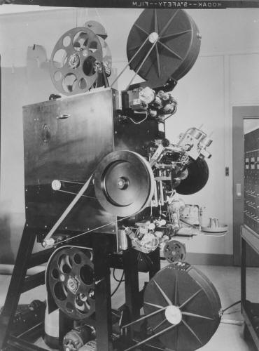 Side view
of the Mark III printer showing the supply reels at the top and the take-up reels at
the bottom. The closed reels are for the raw stock and the open reels are
for the negative. The circular pulley in the center is the heavy flywheel on
the printing drive to insure smooth motion. Side view
of the Mark III printer showing the supply reels at the top and the take-up reels at
the bottom. The closed reels are for the raw stock and the open reels are
for the negative. The circular pulley in the center is the heavy flywheel on
the printing drive to insure smooth motion.
After
our discussion of the Mark III Printer on July 11 [1957], I promised to write
up a description of the principle which distinguished it from the
earlier Mark II model. The incentive for developing the Mark III was
primarily to get increased printer speed and hence print output.
The
only ways to accomplish this were:
1) Increase light source brightness,
2) Increase lens speed,
3) increase printer slit width.
The light source
problem was being considered but tungsten lamps were the only practical
solution at the time and were already being used at maximum brightness
levels. The printer lens speed was already at the borderline of adequate
image sharpness and no substantial increase seemed feasible. This left
only the printer slit width. Printer speed being directly proportional
to slit width
indicated it
would be desirable to find some way to increase this by a factor of two
or more.
In
the Mark III the slit width is limited by two things: 1) for anything
but zero "droop" correction, the image of the negative does
not coincide with the print film at all points but rather it intersects
the print film at an angle which increases with increasing
"droop" and which is equal to twice the bridge angle (i.e.
angle of incidence of light on print film). This means that the image is
in focus on the print film at only a single line and thus a given point
on the negative is in focus only during the instant it crosses this
line. On either side of this line it goes out of focus to a degree
depending on the distance and on the angle. For a droop corresponding to
the requirements of a theater like the
Rivoli, the bridge angle is about
45°
and the image makes an angle of 90°
with the print film. In this case a slit width of about 0.010 inch is
all that can be tolerated, before image blur becomes objectionable.
The
other factor that limits the slit width is the amount of transverse
motion of any given image point (especially near the edge of the
picture) due to the change in magnification resulting from the
oscillating lens. This change in magnification is necessary to produce
the corrections for keystoning in the theatre (K-correction) and for
vertical line curvature from the camera lens distortion (A-1
correction). For the case of K-correction alone, the transverse motion
at the edge of the film occurs at a rate of almost 1/5 that of the
longitudinal motion picture and hence a slit width of 0.010 inch allows
a transverse blur of about 0.002 inch multiplied by an additional factor
because the effective slit width is increased by the oblique incidence
of light onto the film print. The addition of A-1 correction aggravates
this transverse blur still further, particularly in the upper corners of
the frame.
|
Further
in 70mm reading:
Todd-AO Equipment
Catalog
Part
1:
Todd-AO
Distortion Correcting Printing Process
Part 3:
"Oklahoma!"
Printing
Operation
in the Todd-AO Mark III Printer
The Rivoli Theatre
Internet link:
|
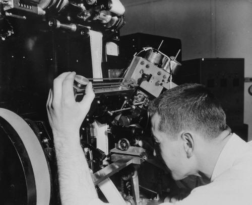 Benny Grinsewitz focusing the optical system. Benny Grinsewitz focusing the optical system.
In
the Mark III printer the optical system has been modified so as to
eliminate both the blur due to the angle between image and print film
and the transverse blur due to K-correction. The first of these was
accomplished by replacing the Amci (90°
roof type) prism at one end of the bridge by a regular 90°
prism identical to the one already being used at the other end of the
bridge. In this way the image and the print film were caused to coincide
at any bridge angle, neglecting for the moment the curvature of the
negative over the guide rollers and the curvature of field of the
printer objective lens system. Both of the latter are far less important
in causing blurring of the image than certain other effects.
This
change in the optical system by itself, without the oscillating lens
action, would cause a transverse blurring which is comparable to that
mentioned previously since, in this case, the instantaneously-formed
image on the print film is itself keystoned. Thus the image of any
off-center point on the negative does not travel parallel to the print
film during printing but at an angle which increases towards the edge of
the film. Here then lies the crux of the Mark III principle. By
introducing just the right amount of opposite transverse motion for each
point of the image using the oscillating lens, it is possible to
compensate this "intrinsic" keystoning and eliminate this
source of blurring. Now at the same time this will produce the desired
overall keystoning of the image of the frame on the print film because
as each elemental horizontal strip of the negative passes over the
printer slit, it will be magnified by a different amount due to the
oscillating lens just as in the Mark II printer.
In
summary, therefore, the Mark III makes it possible to print a keystoned,
drooped image using a substantially wider slit. The A-1 corrections
however, again cause some transverse blurring which now is most
noticeable in all corners of the frame. This together with the curvature
of the negative and the curvature of field of printer lens (which
unfortunately add to one another, rather than cancel) now limit the slit
width.
|
|
 Printing section showing on left the negative slit illuminated in
straight line & on the right the print stock on the curved shoe & slit
illuminated with a curved line (The B, or “Droop” correction). Printing section showing on left the negative slit illuminated in
straight line & on the right the print stock on the curved shoe & slit
illuminated with a curved line (The B, or “Droop” correction).
When
the Mark III was tested in actual printing operation it was found that a
slit of 0.030 inch or three times the Mark II could be tolerated at a
bridge angle of 45°
and about 0.040 inches at a bridge angle of 38°.
Thus factors of 3 to 4 in speed could be realized, other things being
equal. Actually various other changes particularly in the light source
optical system were made which make a direct comparison invalid.
The
problem of obtaining any given overall frame keystone correction
(K-correction) along with any given droop while at the same time
matching the "intrinsic" printer keystone requires the control
of several factors in the printing system. The focal length of the
printer lens and the bridge angle determine the intrinsic keystone. The
curvature of field of the printer lens and the bridge angle determine
the droop. The overall frame of K-correction is a function of the shape
of the cam which drives the oscillating lens and must be such as to
compensate the intrinsic keystone. Thus for a given K-correction and
droop it will, in general, be necessary to specify the printer lens
focal length, the bridge angle, the cam design and the curvature of the
print film guide or "shoe" which curves the print film to fit
the image curvature. Fortunately a family of useful sets of
K-corrections and droops corresponding to practical theatre conditions
can be realized using only one printer lens focal length, by changing
bridge angles, cams and print film "shoes". A change over from
one sets of these conditions to another is not very simple, however,
because several critical adjustments such
as phasing of the cams with the frame line and balancing the
focus of the oscillating lens are required to obtain best performance.
One
other change in the printer lens of the Mark III might be noted. The
matching of intrinsic keystone with K-correction requires, in general, a
longer focal length printer lens than used in the Mark II and this
introduces a new distortion into the printed picture, namely, a
horizontal expansion of objects near the edges of the picture (in very
much the same way as projection on a curved screen compensates for the
barrel distortion in the camera lens). This is a very undesirable effect
for scenes taken with long focal length camera lenses since now this
horizontal expansion would occur twice, once in the printer and again on
the screen. To eliminate this effect in the printer, an aspherical lens
similar to the type used in the 128°
camera lens was used as one element of the printer lens system (the
element nearest to the negative film). This effectively reduces the
horizontal magnification for objects near the edges of the picture
without changing the vertical magnification and cancels this source of
distortion.
|
|
| |
|
Go:
back
- top
-
back issues
Updated
21-01-24 |
|
|
 Benny Grinsewitz focusing the optical system.
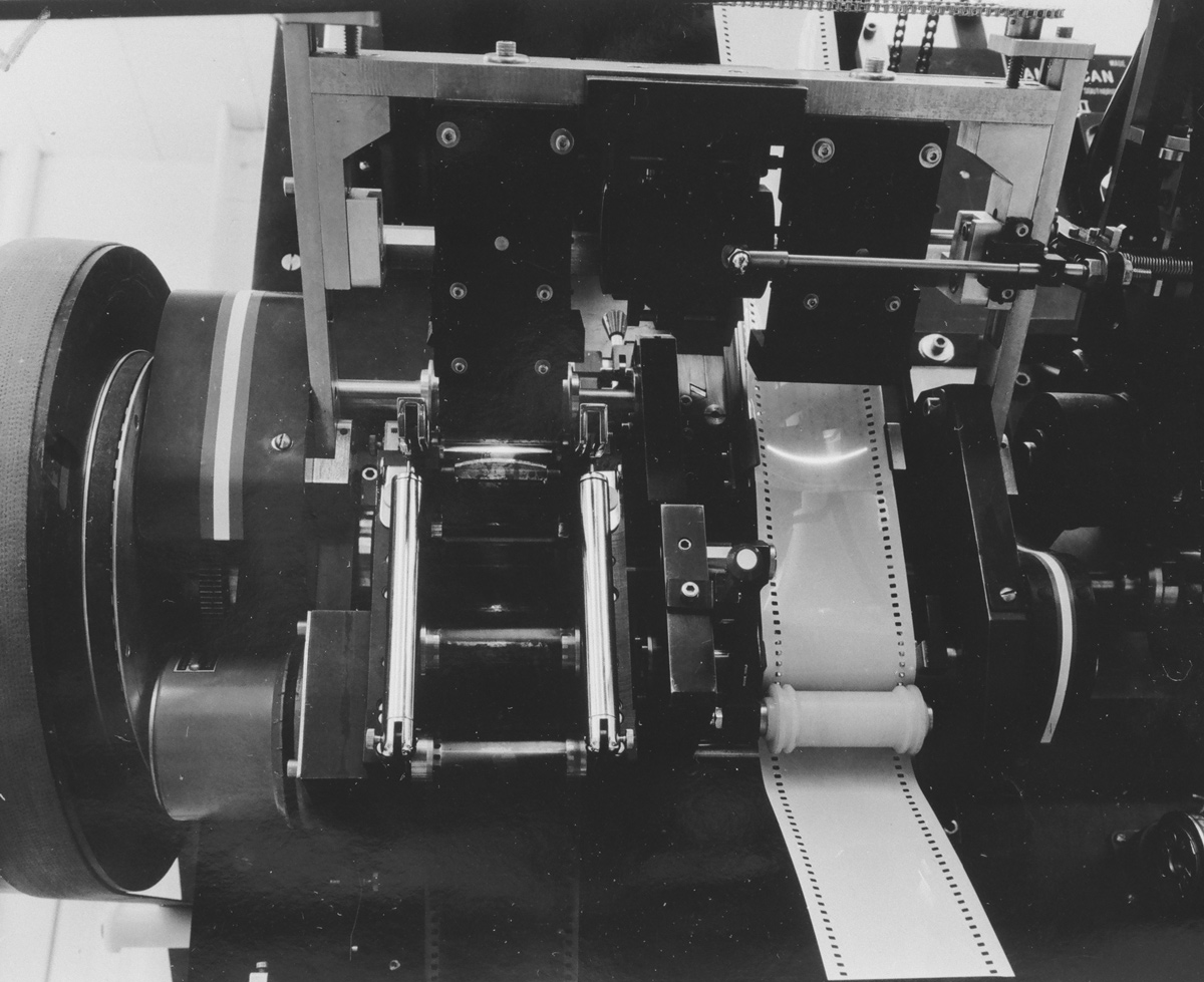 Printing section showing on left the negative slit illuminated in
straight line & on the right the print stock on the curved shoe & slit
illuminated with a curved line (The B, or “Droop” correction).
Printing section showing on left the negative slit illuminated in
straight line & on the right the print stock on the curved shoe & slit
illuminated with a curved line (The B, or “Droop” correction).