
The Waller Flexible Gunnery Trainer
|
Read more
at in70mm.com The 70mm Newsletter |
| Written by: Fred Waller, Vitarama Corporation, Huntington Station, N.Y. | Date: 09.01.2010 |
|
729 Seventh Avenue New York, NY Phone Bryant 9-6745-6746 Cable: Century New York The Waller Gunnery Trainer described in this reprint from the Journal of the Society of Motion Picture Engineers was one of the top secret developments of the war and was on the restricted list of equipment. Each Trainer employed nine Century mechanisms operating in synchronism. Five were used for picture projection and four for the scoring mechanisms or registers (See Page 86). Century Projector Corporation cooperated in the development of this equipment as well as its manufacture. The first installation was made at Pearl Harbor soon after we were attacked [7 December 1941, ed]. The operating record established by this equipment is remarkable and unparalleled in the history of motion picture projection. Operating twenty-four hours per day, seven days a week, and training more than 1,000,000 men, not a single mechanism failed in service to be returned to the factory for overhaul. The Trainer was used by the U. S. Army Air Corps, U. S. Navy. and the British for the final training and retraining of machine gunners. It was declared "Essential to Winning the War". Preliminary training was obtained on less complicated and less accurate devices. It has been calculated that each trainer paid for itself over - two days of operation and thus saved many millions of dollars in war cost, plus the more important saving in men and planes which never can be properly estimated. The experience gained from this service record is now reflected in better, more sturdy Century projector mechanisms which are identical in essential operating features with those used on the Waller Trainer. Century model "C" and model "CC" projector mechanisms for regular theatres are available in all countries of the world, except Canada and the United States, through Westrex Corporation. In Canada they are distributed by Dominion Sound Equipments, Ltd., and in the United States by authorized Independent Theatre Supply Dealers. CENTURY PROJECTOR CORPORATION, July 1946 |
More
in 70mm reading: The Cinerama page Fred Waller's 1950 Diary Internet link: 2010 version |
Summary - The Waller Flexible Gunnery Trainer, By Fred Waller |
|
|
A description is given of the equipment devised to train gunners
to hit fast-moving targets. The more important and novel features are
discussed. The trainer not only reproduces for the observer any desired
environment and target, but also correctly simulates conditions of fire in a
way that otherwise could only be found in actual combat. |
|
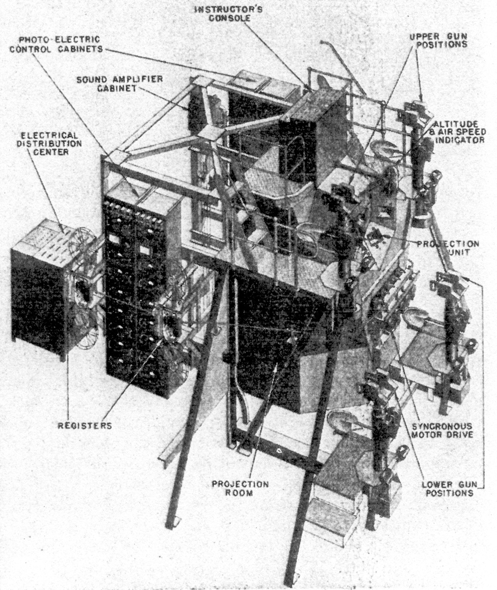 Fig.
1. Bird's-eye view of Waller Flexible Gunnery Trainer-Mark 2, showing
unified assembly of elements. Fig.
1. Bird's-eye view of Waller Flexible Gunnery Trainer-Mark 2, showing
unified assembly of elements.Click image to see enlargement A humorous slant or gag often conveys an idea better than a serious description. James Reddig, one of the Eastman engineers, was asked by another friend of mine how the gunnery trainer had changed from the experimental model he had seen and what it looked like. Jim replied, “Oh, that's easy. You take the end off the Triborough Bridge, put four men on it with their feet dangling in the air, a console like a church organ, and behind that photocells, amplifiers, levers, scanners, and a lot of other things that I cannot understand. Then, take the Perisphere from the World's Fair, cut it into 4 pieces, push the end of the Triborough Bridge into one of the pieces and you have a Waller Gunnery Trainer. It's just as simple as that." As this description and Fig. 1 give you an idea of the size and complexity of the machine, it is obvious that a complete analysis and description of the apparatus cannot be given in one paper, so the following covers the more important and novel features. The purpose of developing this machine was to train gunners, under realistic conditions, to estimate quickly and accurately the range of a target, to track it, and to estimate the correct point of aim when using noncomputing sights. To accomplish this purpose, the Waller Flexible Gunnery Trainer uses a special spherical screen process. This process was conceived by Ralph Walker, a well-known architect, and myself in 1938, and several years were spent in developing the apparatus and overcoming the problems involved. In June, 1940, H. Martyn Baker, an old friend of mine who is a graduate of the Naval Academy at Annapolis, recognized the possibilities offered by the spherical screen process in the training of gunners to hit fast-moving targets. That was the real start of work on the gunnery trainer. |
|
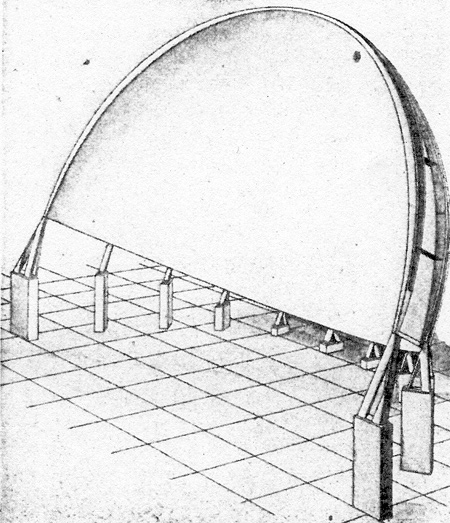 Fig.
2. Perspective view of spherical screen upon which scene is projected. Fig.
2. Perspective view of spherical screen upon which scene is projected.The fundamental theory of the spherical screen process in that for the average individual the perception of distance, beyond about 20 ft, is not so much the result of binocular stereopsis as it is of peripheral vision, relative movement, size of object and atmospheric perspective. By peripheral vision I mean what the eye sees outside of its central area of sharp focus. This screen process simulates what the eye normally perceives by filling a screen, shown in Fig. 2, which is a portion of the inside of a sphere, with a motion picture. The angular dimensions of the screen, 150 deg in the horizontal and 75 deg in the vertical, are nearly those encompassed by the normal human eye, and the angular relationships of any object, fixed or moving, on the screen are the same as those seen by the eye in actuality. Thus, the requirements of peripheral vision and movement perspective are satisfied. In the photography, the size and atmospheric perspectives are reproduced. Therefore, the observer finds himself surrounded by a normal visual effect. The success of the curved screen process in accomplishing this is evident to anyone who has ever seen it. |
|
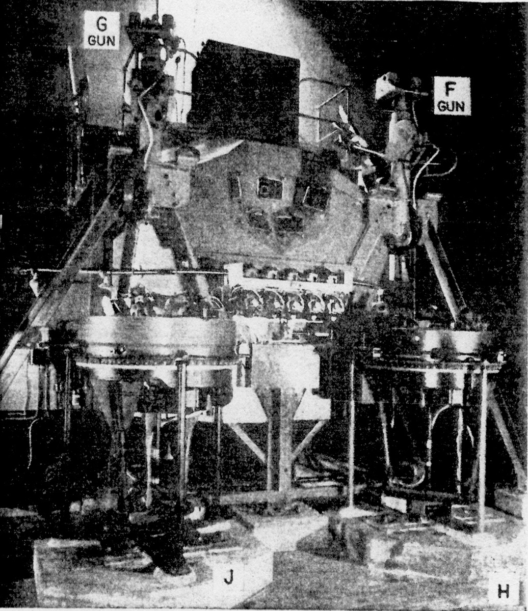 Fig.
3. Front view of trainer showing method of mounting and grouping of guns and
turrets around the projection unit. Fig.
3. Front view of trainer showing method of mounting and grouping of guns and
turrets around the projection unit.Click image to see enlargement For gunnery training purposes, a picture of the desired target, say an airplane, is produced. To the observer this target does not remain more or less fixed upon a single square screen covering only a small angle but moves within his field of vision in an entirely normal manner thus enabling him to exercise his judgment of distance and motion as though he were in the field. . The observer is placed behind a dummy gun, located near the optical center of the screen, with which he attempts to hit the target. By means of suitable apparatus described later, when the trigger of the gun is pulled, and the gun is aimed so that a hit would be made, this fact is instantly announced audibly in the gunner's earphones. This enables the person being trained to make an immediate mental note of the judgment and actions which led to success. In this way the Waller Flexible Gunnery Trainer not only reproduces for the observer any desired environment and target, but also correctly simulates conditions of firing in a way that otherwise could only be found in actual combat. Since anything can be produced on the screen that can be photographed, and since operation of the trainer is independent of weather, time, and the availability of actual equipment, it offers a valuable means of training in preparation for and supplementing actual firing. In order to cover a screen of 150 deg in width by 75 deg in height with motion picture projection, it was found necessary to have 5 projectors to obtain sufficient light on the screen. This dictated the number of cameras needed to take the pictures. The camera consists of five 35mm motion picture cameras synchronously driven and operating as a single unit. This unit has been kept sufficiently small and light so that it can be mounted in the gun or turret positions available on bombers, or be used on a tripod ashore or afloat. The cameras are arranged to cover, to the best advantage, a spherical angle of 150 deg by 75 deg, and each one covers approximately a fifth of this total image. By operating the camera unit in a gunner's position, it photographs what he would see from this same position. In the trainer, these pictures are projected on a spherical screen of the same total angles by means of 5 projectors which are arranged in the same relative positions as the cameras. They reproduce the picture as photographed, that is, as if the gunner had been in the same position which the camera occupied. |
|
The Screen |
|
|
The screen is shown as a section of a hollow sphere of 20-ft radius. The
supporting framework is made of plywood, I-beams and intercostals. The frame
is covered with preformed plywood panels that are screwed in place. The
projection surface of the screen is given a special semispecular finish
which reflects light principally to the center, where the gunners are
placed. By doing this, it minimizes the degradation of the projected images
by cross reflection from one part of the screen to another. |
|
Arrangement of Dummy Guns |
|
|
Placed at even distances around the center line
of the projectors and the center of the screen are 4 dummy guns shown in
Fig. 3. Each gun is mounted on a heavy tubular mount and is free to train
and elevate so as to cover the screen. On the outside of the mount is a
bearing for a seat which slides on 2 tubes so that it may be adjusted for
men of different heights. The seat swings on a horizontal axis and is
supported by heavy spiral springs which are also adjustable for varying
weights of men. The seating arrangement gives full flexibility so that a
gunner can keep his eye in line with the sight. Each gun is provided with a pair of handles, the right one containing a trigger. When the trigger is pulled, the handles are vibrated by a pair of motors in the dummy gun, simulating the recoil of a 50-caliber gun.  Fig.
4. Sighting the target through the Mark 9 gun sight. Fig.
4. Sighting the target through the Mark 9 gun sight.The instructor can disconnect the vibrator circuit if he so desires. On each gun in the original model is mounted a Mark 9 collimator sight. Fig. 4 shows what the gunner sees when he looks through his sight at the target in the field. Subsequently, the trainer has been adapted to train men for sighting with Sperry and Martin waist turrets, Sperry ball turrets, G. E. fire control stations, as well as several different mountings for 50-caliber and 20-mm guns, with and without lead-computing sights, and the Navy Mark 51 Director. Various combinations of these device were installed on individual trainers as required. For training crews for the B-29's, 3 pedestal-type G. E. Directors and one ring-type director are used. |
|
Firing at Target |
|
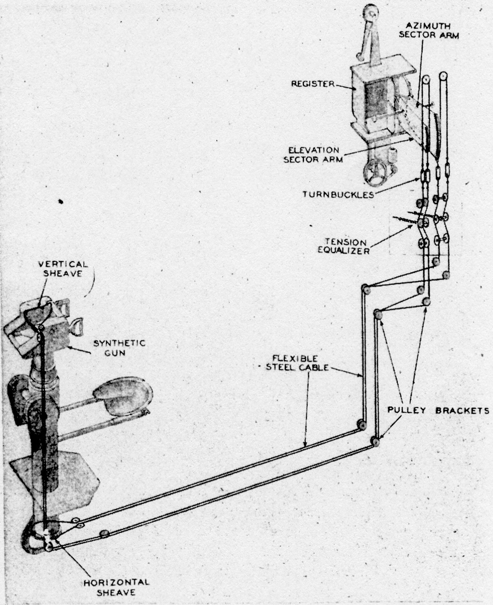 Fig.
5. Schematic drawing showing flexible steel cable system from gun to
register. Fig.
5. Schematic drawing showing flexible steel cable system from gun to
register.Click image to see enlargement As the gunner looks through the sight and follows the target the resulting movement of the gun, in train and in elevation, is transmitted, as shown in Fig. 5, by a pair of light flexible steel cables running over ball-bearing rollers to train and elevate lever arms in the unit called the "register". Each pair of cables is kept under constant balanced spring tension so that stretch or expansion and contraction from temperature changes have no effect on its accuracy. The lever for train and the lever for elevation each connect with opaque masks having a transparent pattern of 2 fine lines. These marks slide horizontally across the face of an aim scoring film in the register unit associated with each gun. Figs. 6, 7, and 8 show details of linkage and scanner bars and masks. |
|
Scoring Mechanism in Register |
|
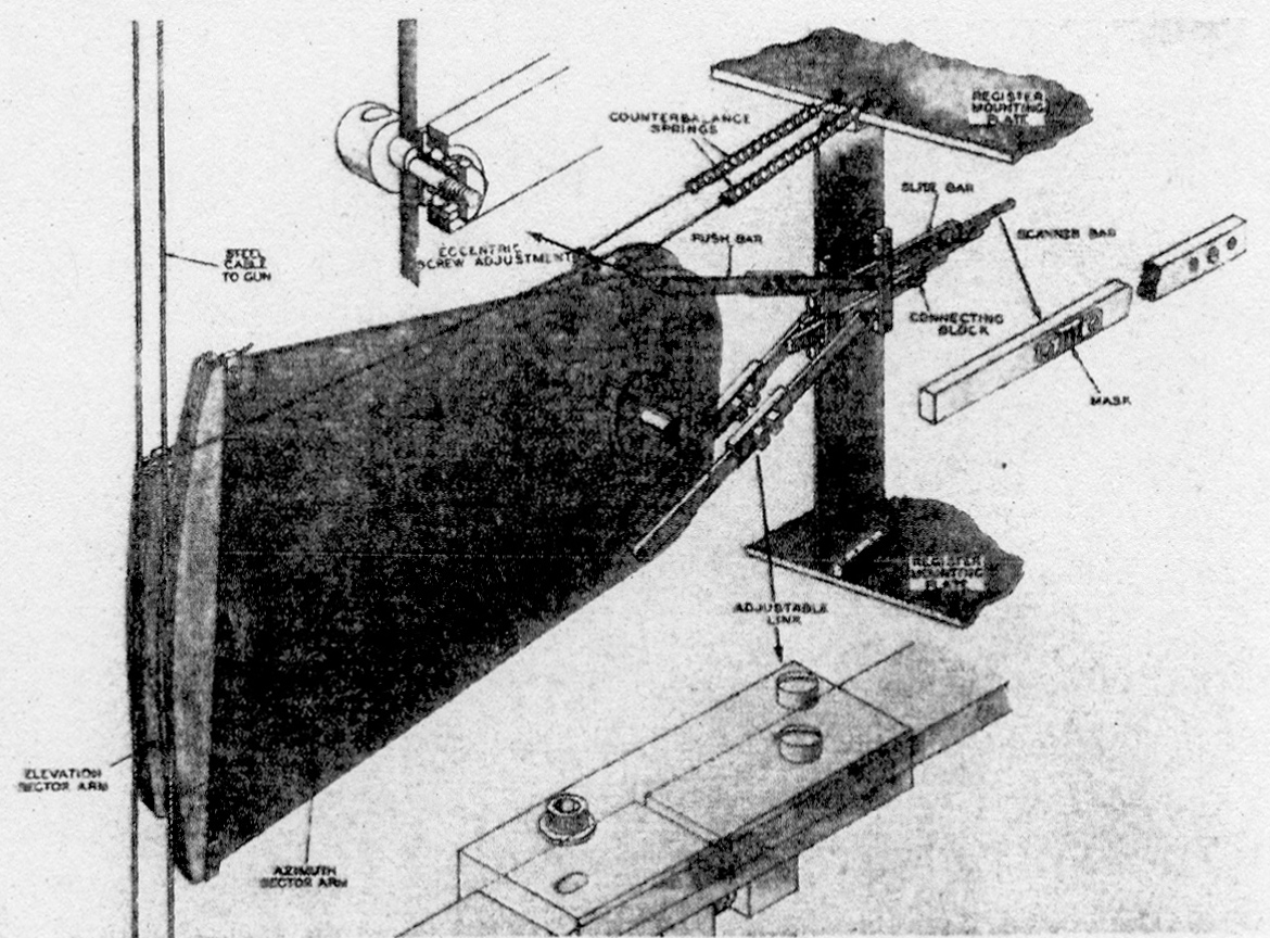 Fig.
6. Close up of sector arm to scanner bar assembly. Fig.
6. Close up of sector arm to scanner bar assembly. Click image to see enlargement The function of the register unit is to determine whether the gun is aimed at any instant to hit the target plane. It is this unit which receives the existing train and elevation from the gun, and if the aim is correct, it provides the means of sending electrical impulses to the instructor's console where the hit recording counter for each gun is located. The register is similar to one of the screen projectors and the film used in the register operates in step with the screen picture films at a speed of 24 pictures per sec. The film used in the register is not a picture film, as may be seen from Fig. 8. but is a hit scoring film specially prepared as described under the scoring machine. There is a frame of register film to correspond to each frame of picture film. The register film is opaque and on each frame of the film are small transparent areas. The areas are so spaced that they represent the position at which the gun should be aimed to hit the target in the position shown by the corresponding picture frame. When the gun is pointed at the correct point of aim, transparent areas of the masks which the levers move will then register with the transparent areas in the film. This allows the light in the register projector to be transmitted to a photocell which, through an amplifier and relay, actuates the hit counter mounted in the instructor's console. |
|
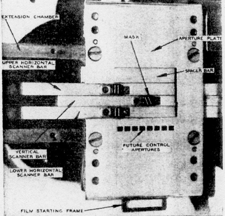 Fig.
7. Close-up view of scanner bar and gate assembly. Fig.
7. Close-up view of scanner bar and gate assembly.Each time the gunner pulls the trigger one burst for his gun is recorded on the corresponding burst counter on the instructor's console. At the same time, the bullet counter for his gun will record the number of bullets that would be fired during the length of time in which he holds the trigger down. If the gunner has his gun pointed at the correct point of aim when he pulls the trigger, he will hear a high pitched tone in his earphones instantaneously and he will score as many hits as the number of bullets fired while he maintained the correct point of aim. If the gunner is not on the correct point of aim when he pulls the trigger, he will still score the burst and the bullets fired but no hits. On trainers adapted for devices where range and aim are fed in separately, 5 counters are used. The fourth records the number of bullets fired while the gunner is putting in the correct range, and the fifth the number of bullets fired while he is aiming correctly. On these trainers the hit counter scores only when both range and aim are scored simultaneously. |
|
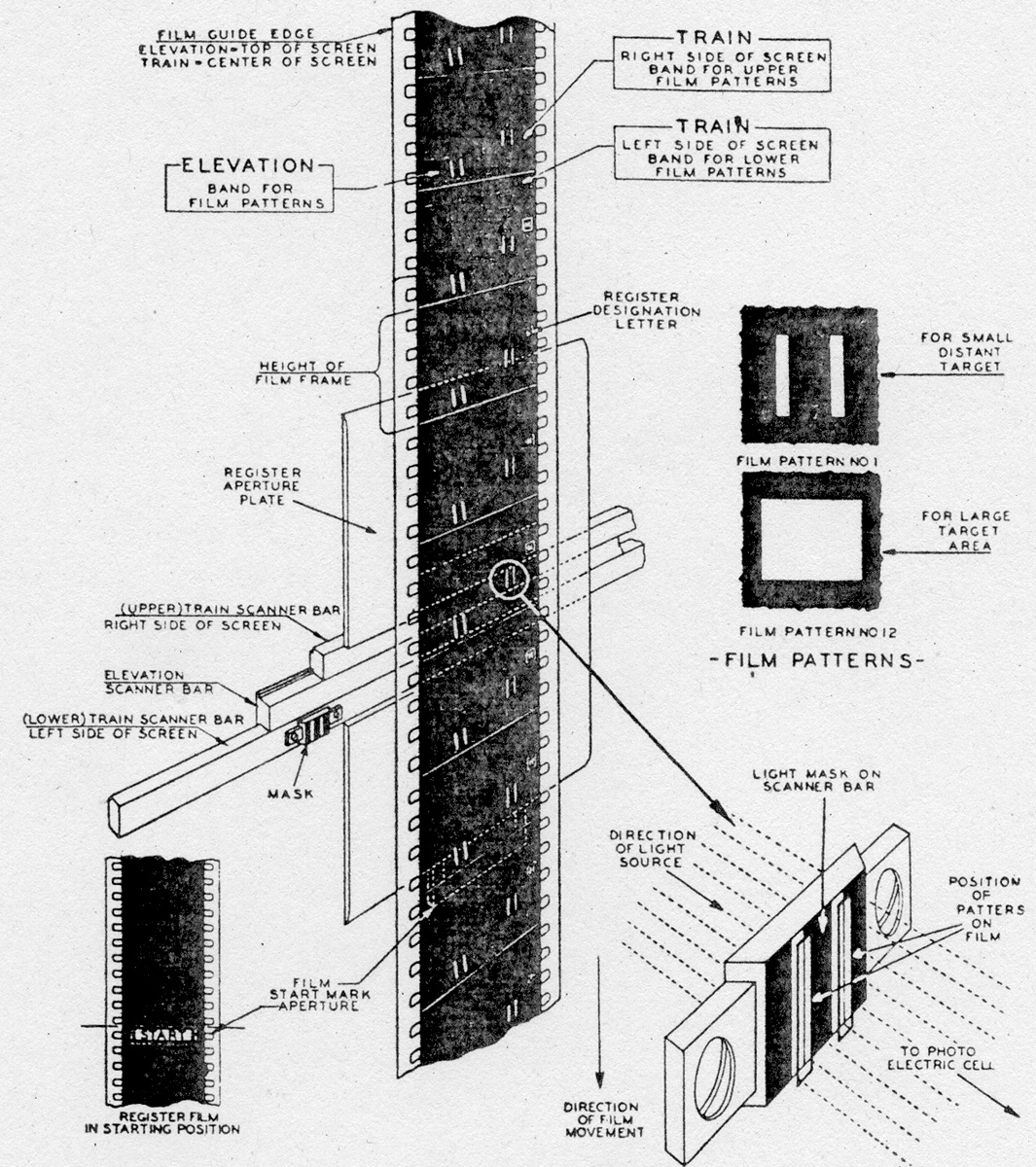 Fig.
8. Schematic drawing showing register film in relation to scanner bars and
method of registering film for scoring. Fig.
8. Schematic drawing showing register film in relation to scanner bars and
method of registering film for scoring.Click image to see enlargement In order that the scoring on this machine may represent actual combat conditions, the scoring film in the register unit may have different-size transparent areas to allow for different-size vulnerable areas and targets, or to allow for the area of the cone of gun dispersion. These areas may be placed on the scoring film at different distances apart. If they are on every other frame, they will record hits at the rate of 720 per min; if on every fourth frame; at 360 per min, etc. By using this method, the gunner will not only score hits in proportion to his accuracy of aim but he will also score hits in the proportion which the vulnerable area of the target is to the area of the cone of fire at the distance of the target. That is, if the target at 600 yards has a vulnerable area of 30 sq ft, and the area of the cone of fire is 300 sq ft, only one-tenth of the number of bullets fired would hit the target. Both of these factors are taken into consideration and the scoring gives a real indication of the man's ability as a gunner. Some branches of the Armed Services desired to omit these features and for them a constant angular tolerance of aim was used and all hits recorded. By using film for the production of the register bands, great flexibility is obtained. |
|
Instructor's Console |
|
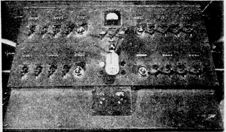 Fig.
9. Close-up view of the control panel on the instructor's console. Fig.
9. Close-up view of the control panel on the instructor's console.The instructor's console is mounted to the upper forward portion of the structural framework, above the 5 projectors. From his position at the console, shown in Fig. 9, the instructor may view the entire screen and the 2 upper gun positions. The console has the following general controls and indicators: (a) A running time meter to indicate total hours the trainer has been run. (b) Switch to illuminate counters when house lights are off. (c) A "still" button which allows instructor to hold pictures on screen for 5 min so that he may point out errors students are making in their aim. (d) A "start" button. (e) A "stop" button. (f) Switch to permit talking to all 4 students at once. (g) Projection room signal light to indicate "ready." (h) Switch to communicate with office or projection room. (i) Microphone head to contact students or projection room. (j) Intercommunicating telephone with projection room. In addition, 3 counters and the following controls are provided for each of the 4 gun positions: (a) Total number of rounds fired. (b) Number of bursts filed. (c) Number of hits obtained. (d) Pilot light which flashes as each hit is scored. (e) Microphone switch so instructor can talk to individual gunner. (f) Vibrator switch by which vibrators on individual guns may be disconnected. (g) Aim projector switch which shows a one-inch diameter ring of light at place on screen at which the gun is aimed. The student does not see this light, since the central spot in his own sight covers it up but it allows the instructor to see where that student is aiming. The ring is projected on the screen by small projector mounted on the gun. (h) Control knob, to return counters to zero. (i) Pilot lights to indicate switches "on” or "off." |
|
The Scoring Machine |
|
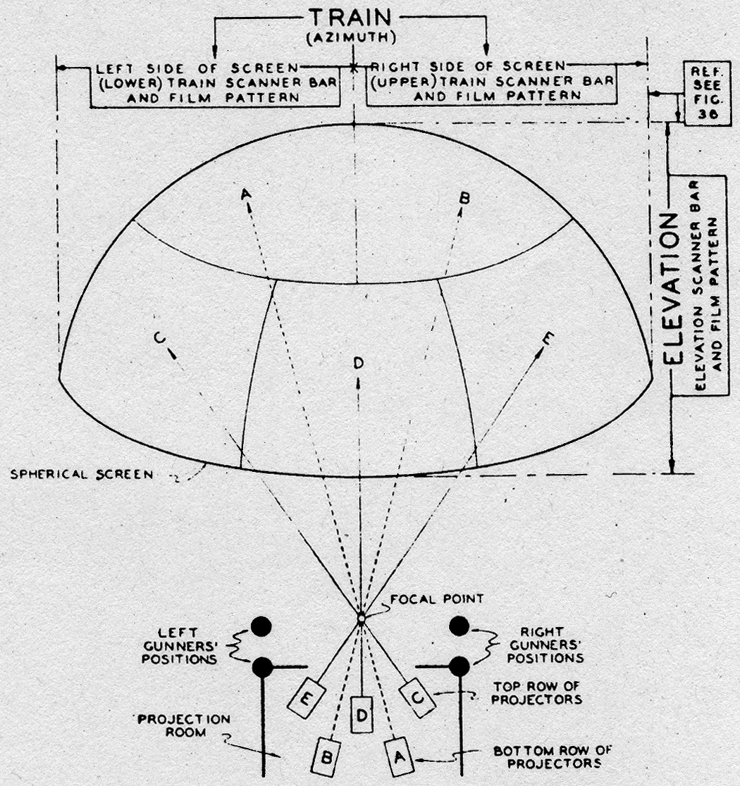 Fig.
10. Schematic plan showing method of projecting mosaics on the screen. Fig.
10. Schematic plan showing method of projecting mosaics on the screen.Click image to see enlargement For the preparation of the aim scoring films which are used in the registers, we have developed a special machine called the scoring machine. This machine consists of the following parts: (a) Five projectors for projecting the films one frame at a time. (b) A 10 ft radius screen laid off in degrees of train and elevation on which these pictures are projected and analyzed. (c) Four pointers in the same relative positions occupied by the guns on the trainer. (d) Four cameras connected to these pointers for making the original negatives from which the scoring films are printed. On this scoring machine, the pictures are analyzed and a plot is made showing the range for each frame of film, that is, each 1/24 sec. Simultaneously, a record is made of the angle of the target, in both train and elevation, in relation to the gun-carrying plane. A record is kept by the cameraman, who makes the original negative, of the air speed and altitude of the gun-carrying plane. With all this information, the Aberdeen Tables give us the time of flight of the bullet. Knowing how many twenty-fourths of a second it will take the bullet to reach the target, we then aim the 4 pointers, which represent the 4 gun positions, at the picture which is that many twenty-fourths of a second, or frames of film, later. This gives the correct angular lead. By then displacing each pointer the number of gunnery mils in both train and elevation which the tables give as the ballistic corrections, we have the correct point of aim. By a system of cables and levers similar to those connecting the gun and its register, each pointer is connected to a scoring camera. This camera makes a master negative scoring band for its gun. When the scoring band is run in synchronism with the picture print from which it has been made, it will record, to within a few gunnery mils, the correct point of aim for the moving target shown on the picture film. |
|
Projector Unit |
|
|
The projector unit is a group of 5 Century projectors operating in
synchronism as a single mechanism. All are of the same mechanical design and
each projects a portion of the whole picture upon the screen. The optical axis of each projector passes through a common point, the focal point of the screen, and radiates to 5 different areas on the screen, as illustrated in Fig. 10. The projectors are designed for use with 35mm motion picture film, operating at 24 frames per sec. The running time of a 3000 ft reel is approximately 33 min. A heat shield, which is a circular heat-absorbing Aklo glass filter and associated mechanisms is located close to the rear wall of the projector. It is mounted on a counterbalanced pivoted arm and operated by a solenoid in conjunction with a limit switch which is related to a sequential circuit. The purpose of the heat shield is to absorb and reduce the heat at the aperture in the film trap and protect the film when still pictures are being projected. Incidentally, during this period the radiant heat from the lamp is also automatically reduced by dimming to a degree but still providing sufficient light for still picture projection. When the solenoid operating the heat shield is energized, it pulls the heat shield into its place just back of the condensing lens assembly, where it absorbs a portion of the radiant heat from the lamp before it reaches the film. |
|
Lamp House |
|
|
A cylindrical lamp house is mounted on the rear of the shutter guard. A
large hinged door extending half way around the housing permits access to
the interior for lamp replacements and optical adjustments. It accommodates
a 2100w incandescent filament lamp as the light source for the projector. An inner tube, which surrounds the lamp, is part of the cooling system. It serves to direct an air stream all around the lamp house to carry away the heat generated by the lamp. |
|
Cooling System |
|
|
The system of forced air circulation in the
lamp house has been devised to remove normal generated heat that would
endanger the film in the projector and to provide cool operating conditions.
It includes the assembly of distribution ducts and air tubes associated with
the projector. They in turn are connected to an air supply and exhaust
system provided in the building. The air is forced in at the top of the lamp house, streams past the full length of the lamp all around the bulb as directed by the air tube within the house, and the heat is carried off through the exhaust at the bottom of the house to be dissipated at a distant point. An additional cooling system is provided for the film. It is devised to force a high-velocity sheet of air downward on both sides and over the entire surface of the film in the film trap. The air is distributed through a forked inlet pipe connection on the driving side of the projector and passes through the center wall to the film or operating side. One tube leads to the nozzle on the film trap, the other to nozzle on the film gate. After the cooling curtains of air flow past the film surfaces they circulate about in the immediate vicinity of the mechanisms in the projector. |
|
Main Drive |
|
|
Each projector is driven by its own electric motor, but all
motors are mechanically coupled together and held in synchronism by an
arrangement of beveled gears on a common synchronizing shaft that keeps all
projectors running at a speed of 24 frames of film per sec. |
|
Framing Motor |
|
|
An additional motor called the framing motor mechanically
connected with the synchronizing shaft, serves to bring the projector
mechanisms to a stop with the film in frame and shutters open so that the
still picture projected is properly composed on the screen. |
|
Photoelectric Controls |
|
|
The photoelectric controls of the trainer
designed by W. Robert Dresser, are most elaborate and although not covered
here could easily be the subject of an entire paper. |
|
|
Go: back
- top - back issues
- news index Updated 21-01-24 |
|