
Matchline Elimination |
Read more
at in70mm.com The 70mm Newsletter |
| Written by: RCB - Richard C Babish | Date: 09.01.2010 |
 Click
image to see enlargement Click
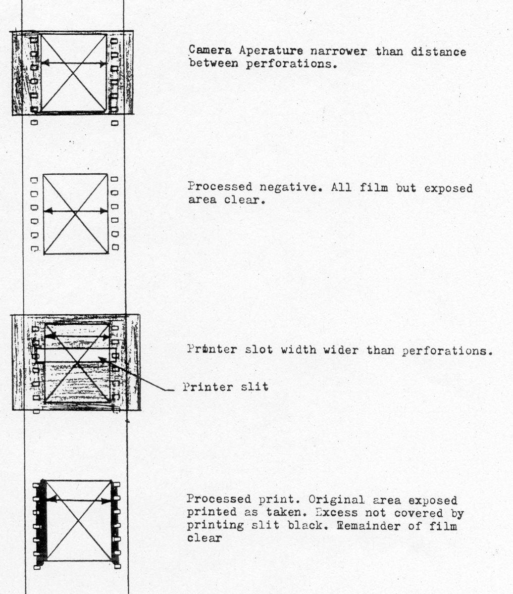
image to see enlargementMatchline elimination begins in the camera and continues through the film handling process to the final projection. Since the method employed presupposes uniformity and initial equality in both portions of the overlap area, anything disturbing this relationship seriously jeopardizes the possibility of achieving a successful blend. Since the width of the match line is so small, careful attention must be given to the complete elimination of each effects extending right up to the edge of the perforation. In the camera, four possible sources of trouble exist. These are edge vignetting, or masking, edge reflection, scratching and pressure exposure. No full or partial obstruction must exist in the complete optical path to the film plane for the full width between perforations. The inside edge of the aperture must not reflect light back into the film frame. Due to the grazing angle of incidence, a fairly high degree of reflectivity exists even with the flat black paint, and of course if paint should be chipped off, the reflectivity of the plating is high. Scratching and pressure exposure in any portion of the frame area is of course undesirable. Unlike the two previous troubles which are confined to the vicinity of the aperture and the optical path, these two latter troubles may originate at any stage in the handling of film. Pressure exposure is confined to film in the raw state and is fairly unlikely to occur without accompanying scratches. However, it often accounts for the broading of the effects around a scratch. The foregoing discussion applies also to printing. Here, the opening of the aperture and the machining of the inside of the sprocket drum (in some continuous printers) must not cause any vignetting effects extending into the film plane. The design of the illumination system too, must be such that the illumination is uniform across the full width of the aperture. At times the illumination appears to drop off rapidly to the edges. Again, it would be desirable to obtain a film strip showing printer uniformity. Except for pressure exposure, all the preceding problems may also be encountered in projection with gigolos removed. In projection, the primary requirement is that for any point within the overlap area the illumination contribution from both projectors be equal in magnitude and color distribution in the absence of gigolos. Because there is a considerable reduction in illumination from center to corner of a panel, it follows that this requirement cannot be met exactly. Fortunately, over the match-line width the effect is small. With present equipment, the most obvious method of approaching these particular problems is to strive to use lenses as nearly equal in focal length as possible with preference being given to longer focal lengths. |
More
in 70mm reading: in70mm.com's Cinerama page Internet link: |
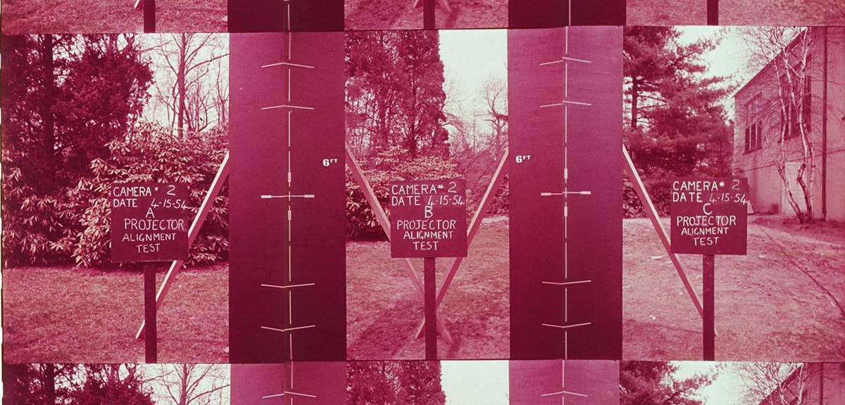 3-panel
projector alignment test footage, photographed with Cinerama camera 2 outside the Oyster Bay tennis court
on 15 April 1954. 3-panel
projector alignment test footage, photographed with Cinerama camera 2 outside the Oyster Bay tennis court
on 15 April 1954.Click image to see enlargement When vignetting means are added, the effect is in general a complex combination of two functions. One is the effect of the vignetting means itself and the other is the additional spreading effect due to the fact that the means are not in the focal plane and are therefore out of focus. The latter will be treated first and will be termed simple vignetting. If the vignetting means is physically or optically positioned in the focal plane, the out of focus effect is reduced to zero. As the means are displaced from the focal plane, the means become in effect an additional aperture stop which more or less rapidly over positions of the match-line area limit the rays contributing to the illumination at any particular point on the screen. Since it is only one of the several aperture stops, its effect is determinable only in terms of the entire system and is therefore complex. In the ideal case of a distortionless thin lens of a narrow field angle fully and uniformly illuminated, a straight edge displaced from the film plane by an approximate distance could yield perfect vignetting. To control the vignetting rate would merely require shaping the aperature appropriately, a relatively simple procedure. Because of the known deviation from the "ideal" lens system, this method was never actually tried, although it might very well be worth testing, When additional vignetting means are employed, the effects of the simple vignetting serve to further spread the pattern while its own effects are in a sense diluted. The additional spread is of curse a function of the entire optical system, the type of vignetting means employed and the separation of the means from the focal plane. By keeping the means close to the focal plane, some, but not all of the contributions of simple vignetting can be minimized. |
|
|
In an attempt to obtain controlled vignetting, other methods have been
proposed. These include optical density wedges, and "time" wedges of two
types. In projection, optical density wedges include optical materials
inserted into the beam or photographic wedges introduced at some stage
of the film process. Optical wedges would probably fail at the
temperatures encountered. Density wedges could be introduced as far back
in the system as the camera. This was considered and avoided because of
the additional complexity involved at a time when cost was of
tremendous importance, because of the uncertainty of the accuracy after
passing through several processing steps, and the fact that error
introduced accidently might possibly be uncorrectible. If the wedge is
introduced in printing, only one photographic process is employed, the
process is brought into the lab where it is subject to more accurate and
comfortable control, and in the event of error only one print is
spoiled. The great advantage of the photographic wedge is that if these
failings are overcome, the proper alignment of the panels and the proper
vignette are achieved simultaneously. While shrinkage effects can be
seen immediately and may be corrected simply, intercutting of materials
with different shrinkage is prohibitted because the two types of error
become apparent unless rapid effective means for adjustment are
provided. In an attempt to obtain controlled vignetting, "time" wedges were conceived. In effect, illumination is controlled by varying the time in which light is permitted to fall on any particular areas. Two general forms are possible. the wipe oscillated laterally and the serrated teeth oscillated longitudinally. The wipe has received the least attention although it possesses many advantages. In the wipe, the edge close to the film plane is oscillated back and then forth during the open periods of the shutter. The reversal periods are then covered by the shutter so that more linear portions of travel are used. The edge could be vibrated at a very high rate if desired although if vibrated in simple harmonic motion the exposure gradient is greatest at the edges of the match-line making adjustment more critical. The first mentioned method is simplest. Some of its advantages include the fact that there are no pockets to collect dirt. Thickness is relatively immaterial since the edge may be chamfered, and the individual effects of distortion are readily corrected with good accuracy in the field with a small abrasive stone. The amplitude of oscillation is relatively small. A disadvantage is that projectors must be phased to prevent flicker. |
|
|
The saw-tooth form is more familiar. In this form, the thickness of the
material alters the appearance of the form as viewed from the aperature
stop and consequently affects the rate at which the edge is vignetted.
The form is most seriously affected in the corners. If complex
machining is to be avoided thin sections are mandatory. A some what
compensating feature is that tooth form may be altered to control the
vignetting rate. However, since the teeth are small, the tolerances
imposed are also small. In general, the amplitude of oscillation should
be equivalent to many times the pitch to minimize end effects occurring
at the beginning and end of exposure through the shutter. The exposure
time at any point ideally coincides with the passage of an integral
number of teeth. |
|
|
The actual rate of vignetting is therefore a function of tooth
shape,
position, pitch, thickness, optical system as a whole, shutter opening, the
entire geometrical form of the linkage and its timing, and lash and play
of the mechanism. Brief reflection shows that shutter, pitch, linkage
and mechanism effects can only contribute to the "beaded" appearance of
the vignetted edge or alterations between light and dark patches at
about the pitch-interval along the length or portions of the lengths of
the match-line area. If this effect can be reduced satisfactorily by
phasing or any other adjustment, these components may then be
disregarded in any further analysis. There remains tooth shape,
position, thickness and optical system. This latter indicates that any
solution may require reinvestigation whenever the optical system is
altered. Position, in general, should be close to film plane, so that simple
vignetting does not broaden the pattern, allowing teeth of the
largest size to be used (an aid in manufacture and maintenance since
larger teeth reduce the dirt problem). Test have shown that the present location is the proper one for present Gigolos. Only a few thousandths of an inch tolerance remain before showing perforations, while edge effects in the film extend considerably within this margin. These must be eliminated. There seems to be little reason at present (in view of the other large errors still remaining) to depart from the simple linear tooth form presently employed until these other discrepancies are corrected. Associated with tooth form is the disposition of these teeth presently on a straight line. This linear array presupposes distortion-free camera and projection optics. It is well known fact that the camera lens is only distort1on-free in a relative sense; the fairly rectilinear appearance on the screen is due in good measure to partially compensating distortion in the projection lens. However, the giggolos are imaged only by the projection lens and there fore no compensating factors exist. The blend pattern consequently suffers from considerable "pincushion" distortion on the screen. As a result, when gigolos are aligned "parallel" and are adjusted to a good blend on the horizon line, the upper and lower portions of the match area are progressively brightened. These results have been substantial by photographic records. This affect obviously is not correctable by tilting the gigolo teeth. In previous discussions, it has often been suggested that a curved base line could approximate a correct linear appearance on the screen. The obvious disadvantage has been the cost of machining. At the time thinner gigolos were tested, a set of curved base teeth (bent by hand) were tried and shoved considerable promise. This set installed in "C" booth (tennis court) only, has since been removed as it was difficult to maintain adjustment of the flimsy piece. It is suggested that other approaches to the manufacturing problem be investigated, in particular the recently developed photo-mechanical etching techniques of Buckbee-Meers in Saint Paul Minnesota. |
|
|
The last item of concern is spacing of the pitch-line in BAKER. This
setting is based on a computation assuming a thin lens. While
reasonably accurate for approximating the proper value for an ideal thin
lens and diffuse illumination, the assumptions can be seriously
wrong when applied to a practical system. For instance, if the lens had
a sufficiently large rear element to accept the fill cone of
illumination from the lamphouse, the chief rays would be nearly parallel
in the film space implying that the gigolo teeth pitch-line spacing
should very nearly equal the match line separation on the film, quite
different from the present case. Test on the present system in the
TENNIS COURT with a 3½ inch lens in Baker booth show that the
computation is very nearly correct for at least this focal
length, due to the fortuitous geometry of the aperature stops. The error
of about 0,0015" on the average is within the preusion of measurement.
In this test variations of about 0,012" in this measurement were due
to the slight pile up of dirt in the teeth, shoving the importance of
cleanliness and indicating that teeth should be eliminated if possible. |
|
|
Go: back
- top - back issues
- news index Updated 21-01-24 |
|