
Todd-AO How It All Began |
Read more at in70mm.com The 70mm Newsletter |
| Written by: Brian O'Brien, Jr. American Optical Company. Brian O'Brien, Jr. was employed at American Optical Company during the development of the Todd-AO process 1953 - 1957. He was generally in charge of planning and development of picture production equipment. | Date: 03.07.2017 |
Understanding the Todd-AO Process |
|
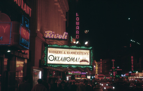 After
three years of research, development and production, the first film in Todd-AO opened
on Broadway. Picture by Don Whitney After
three years of research, development and production, the first film in Todd-AO opened
on Broadway. Picture by Don WhitneyTo understand the Todd-AO process and the reasoning behind it I must go back to some "ancient history". A man named Fred Waller had the idea that if you could obtain a truly wide angle picture and project it, the realism to the observer would be greatly enhanced. He was, of course, completely correct. For example if you photograph a cavalry of horses coming toward you and sweeping past using conventional narrow angle lenses (and this includes CinemaScope), the camera never sees the sides of the horses. If this is now projected on a screen, even a wide curved one wrapped around the audience, as the horses go off the screen they all turn facing you and gallop sideways. This is a subtle effect, but the fact that you never see the sides of objects destroys the participation effect - the sense of being in the middle of the action. Fred Wallers approach to obtaining this true wide angle photography was, of course, to use three cameras pointing to the front and sides with their fields just touching. When these films were projected on a deeply curved screen from projection booths on the orchestra floor, the wide angle was preserved and the participation effect was very impressive. However, there were obvious technical problems. The join lines between the projected images exaggerated the difference in jump and weave of the different projectors. This was partially hidden by placing a vibrant comb at the edge of the projector gates to blur the image sufficiently so that the motion was less noticeable. Color matching of the three prints caused great additional expense. They started the match from the left screen print, and they often had to make as many as 150 right screen prints before they had a satisfactory color timing match. Associated with Waller were the news commentator Lowell Thomas, Buzz Reeves of Reeves Soundcraft and Michael Todd. Mike Todd was a very colorful person. For many years he had been everything from a circus side show barker to a successful Broadway producer. His financial fortunes fluctuated, to say the least, but his credo was "I am often broke, but never poor", and his spending rate was more or less constant whether he had any money or not. When he got associated with Cinerama he was badly in debt both to the income tax people and other creditors to the tune of more than a million dollars. As a result his partners in Cinerama held on to his Cinerama stock with the agreement that he could have it when he got out of debt. With his reputation among the Wall Street bankers as a financial plunger, his partners figured he could never raise that kind of money so "honest" businessmen that they were sold Mike Todd's stock without telling him. Unfortunately for them they had not reckoned with Mikes many good and wealthy friends. He raised the money, paid off his debts, and went around to collect his Cinerama stock that they had sold. Well, to make a long story short, he could have had the whole bunch of them thrown in jail so they paid him off handsomely. That is how he got the seed money for his next project. |
More in 70mm reading: Brian O'Brien, Jr. tracks American Optical Co's development of the Todd-AO process in70mm.com Presents: You are in the Show with Todd-AO This article first appeared in The 70mm Association Newsletter in 1995-1997 in four parts Internet link: |
Mike Todd is on the phone |
|
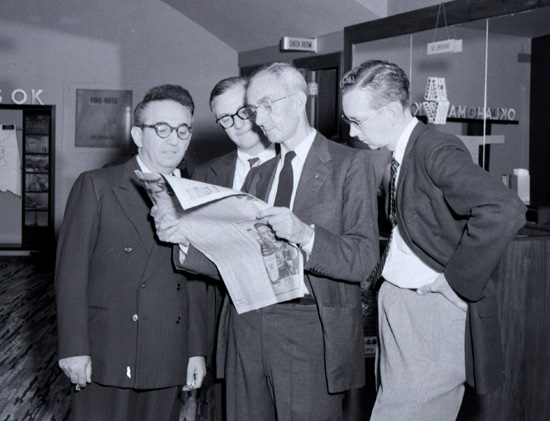 Dr
Brian O'Brien (with newspaper), Brian O'Brien Jr. (to the right) and two
people from the Rivoli, reads "Oklahoma!" reviews in the foyer. Picture from
Optical Heritage Museum. Dr
Brian O'Brien (with newspaper), Brian O'Brien Jr. (to the right) and two
people from the Rivoli, reads "Oklahoma!" reviews in the foyer. Picture from
Optical Heritage Museum.In 1952 I was working for the American Newspaper Publishers Association Research Lab in Pennsylvania. I got a call one night from a fellow who had worked briefly at the laboratory, Warren Millais. He said Mike Todd wanted to talk to my father, and how he could be reached. At that time my dad was director of the Institute of Optics of the University of Rochester. The Institute had been built by him starting in 1930, but he had agreed to join the American Optical Company as Vice President for Research, although this was being kept quiet while the University was in a fund raising drive. My father was a college professor, uninterested in show business, and had never heard of Mike Todd (a fact that I do not think Mike ever completely forgave him for during all their years of friendship), so when Mike called him late one night saying he wanted a meeting, my dad was naturally cautious. They agreed to meet at a bar across from the Rochester airport a few nights later. My father took along a graduate student of his, Walter Siegmund as a witness. Mike arrived in a chartered airplane, and they sat down to talk. Mike asked if my dad knew about Cinerama - he had not, so Mike described the process and then laid down his requirements. "What I want is Cinerama out of one hole. Can you do it?" After some thought my dad said that it probably could be done. Mike said "Great, I want to hire you as a consultant to do it". "Whoa, hold on" my dad said, "no one person can do this. It will take the resources of a large organization, and the three in this country capable of it are Eastman Kodak, Bausch & Lomb and American Optical". After his experiences with the financial community Mike was very suspicious of large corporations, and would have nothing to do with them. After some more discussions they parted on that note. |
|
"Let’s talk business" |
|
|
Every other night for three weeks Mike would call my dad, usually after 10
PM, trying to persuade him to take the job personally (Mikes calls always
came from his switchboard in New York even if Mike was in Belgrade or Los
Angeles). Finally, he called one night and said "OK Doctor, I give up. I
have been looking into the companies you mentioned and American Optical
looks like the best bet. What do I do now?" "Fine" said my dad,
"I am having
lunch with Walter Stewart, President of AO [American Optical] next Tuesday.
Why do you not come up to Southbridge and have lunch with us?" "I will be
there", said Mike and hung up. The following Tuesday Mike showed up in
Southbridge (AO headquarters). My dad introduced him to Walter - Mike
plunked a certified check for $60,000 down on Walters’s desk and said "let’s
talk business" - and that is how it all started. |
|
Corporation Forming |
|
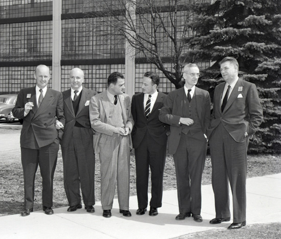 VIPs
at American Optical. In the middle Mike Todd talking with Fred Zinneman, and
Dr. Brian O'Brien talking to Oscar Hammerstein to the right. Picture from
Optical Heritage Museum. VIPs
at American Optical. In the middle Mike Todd talking with Fred Zinneman, and
Dr. Brian O'Brien talking to Oscar Hammerstein to the right. Picture from
Optical Heritage Museum.After Mikes meeting with Walter Stewart there ensued a period of corporation forming and contract writing. Mike had assembled a group he called Magna Pictures which consisted of himself, George Skouras (youngest of the threes Skouras brothers), Lee Shubert (head of the Shubert theatre chain) and Joe Schenck, retired founder of Paramount and one of the grand old men of Hollywood. The intent was that Magna would produce the pictures in the new process. Then a joint corporation between Magna and American Optical was formed to develop the process, and to manufacture and lease the picture making equipment, as well as sell the theatre equipment. Mike wanted to attach the O'Brien name to this new company, but my dad declined. After all, the concept was Mike's and the work was to be done by A.O. and so they settled on the joint name Todd-AO. This was the time I came on board. At first Mike wanted me to work for him but Walter Stewart convinced me that with my technical background I could do more good with A.O. I was in charge of the development of the picture production equipment (as opposed to the theatre equipment) and my father, who came to A.O. as vice president for research was, of course, in charge of the whole development project. |
|
35mm just would not do |
|
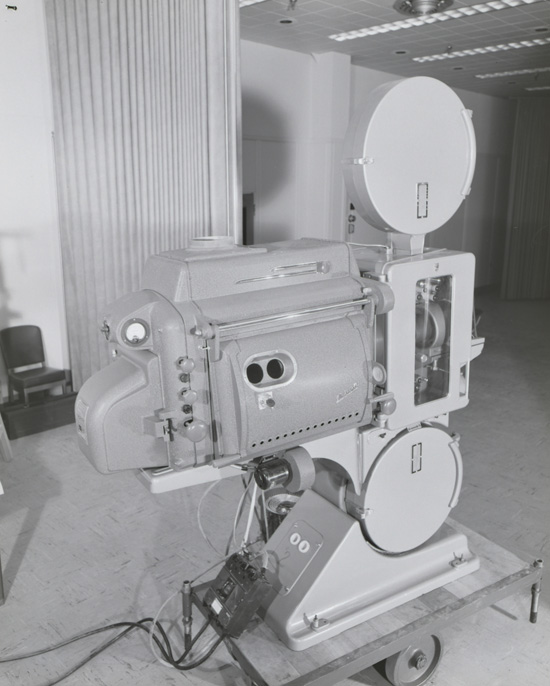 The
Todd-AO projector made in Holland by the Philips company. Here as a
prototype, on a trolley, installed in Southbridge, in the American Optical
Research Center's half-scale Todd-AO cinema. Picture from Optical Heritage
Museum. The
Todd-AO projector made in Holland by the Philips company. Here as a
prototype, on a trolley, installed in Southbridge, in the American Optical
Research Center's half-scale Todd-AO cinema. Picture from Optical Heritage
Museum.From the beginning it was obvious that to fill anything like a Cinerama screen the standard 35mm image just would not do. First of all with photographic emulsions of that day (and even today) the required magnification would produce a very unsharp and grainy image. Moreover, one could not pump enough light energy through that small gate to give a decently bright screen image. Since the screen dimensions would be about twice a normal theatre screen a film size about twice normal would be needed. This would allow theatre magnifications very nearly those in use at that time. The double film size would give four times the gate area and hence four times the light flux through the gate. Off and on for many years larger film format had been tried with varying success. I believe the early showings of "Wings" in the 1930s was on 70mm using Ernemann projectors, and others had tried it. Many of these tries had a common problem, namely flutter of the large film in the gate. This was made worse if they tried to pump a high light flux through thereby increasing the heat and hence the expansion of the film. My father and I were pondering this problem one day in his office, and it occurred to me that the way a monocoque airplane wing is made stiff is to curve the thin sheet metal. With the aid of a couple of ships drafting curves (a very long radius) we curved a piece of film, and sure enough it became stiff and resistant to deformation. I am sure you have noticed that the gate of a Norelco AA11/DP70 has a slight curve with the film held in place by those flexible steel bands. You might ask how focus is maintained over the field with the film curved. It is very easy to design a lens with an inward curving field (in fact one of the lens designers’ usual problems is to produce a flat field lens). This curved field is, of course, nearly spherical and not cylindrical like the curved film. However, the film curvature could be so small that nearly fitting a spherical field to this cylinder was possible, and thus the film flutter problem was solved. But I get ahead of the story. |
|
Audience Participation |
|
|
The obvious next problem was cameras to photograph a large format picture,
and a lens to give the true wide camera angle. Other attempts such as
CinemaScope projected on a wide screen, but the maximum angle the camera
would see was about 88 degrees. The result was a complete loss of the
audience participation effect. Visualize a screen wide charge of horses
coming toward you and sweeping past you projected on a wide screen. If the
camera covered only narrow angle it never saw anything but the front of the
horses, and as they went off the sides of the screen they would side step as
they turned to face you since the camera never saw the sides of the horses.
This effect is subtle, and you probably would not notice it directly, but
the participation effect is destroyed. A perfect comparison was provided by
an airplane landing in Kansas City airport, first in Cinerama (which, for
all its faults, was a true wide angle process) and the CinemaScope film "How
To Marry A Millionaire" where they had a landing on the exact same runway.
In Cinerama you just feel the approach, flare, and touchdown, while in CinemaScope it was just a flat movie (as a pilot and flight instructor I was
especially conscious of this). Therefore, to produce the audience
participation effect of Cinerama on one piece of film, a truly wide angle
lens was needed. |
|
Lens Design and Film Format |
|
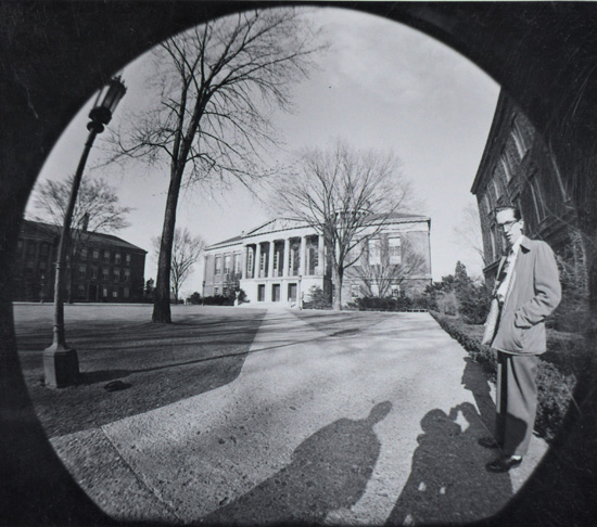 One
of the first pictures taken with the "Bugg Eye" lens and a still camera, in
front of the University of Rochester. Picture from Optical Heritage Museum. One
of the first pictures taken with the "Bugg Eye" lens and a still camera, in
front of the University of Rochester. Picture from Optical Heritage Museum.We enlisted Dr. Robert Hopkins to produce the required wide angle lens. Bob Hopkins was one of my father’s former graduate students and had succeeded my father as director of the Institute of Optics at the University of Rochester and was one of the world’s premiere lens designers. Since time was extremely short many things were done simultaneously. Bob started on the lens design before the final film format was settled upon. The film format was not finalized because there were no cameras. There was a 70mm film standard in existence, but it was, primarily, an instrumentation format with very poor perforation design. The other two perforations were, of course, the Bell & Howell so called "negative" perforation that was flat on top and bottom with rounded ends, and the rectangular Kodak "positive" perforation. The old Bell & Howell perforation dated from the early days of register pin cameras, when it was easier to produce circular rods to close tolerances and then just grind two flats for the vertical registration. The Kodak perforation, on the other hand allowed for much better control of the registration. The 0.122 mm radius corners with the flat top, bottom and sides permitted an interference of 0.0001 inch in the vertical dimension on both sides of the film, and full fit pin (0.0001 inch lateral interference) on the register side of the film and a slightly narrower pin on the other side of the film to allow for the film shrinkage which is greater across the film than along it. The pins have their corners cut flat on a 45 degree angle. This now allows the space between the flat corner of the pin and the rounded corner of the film to distort enough to accommodate the .0001 inch interference. The result is a much better registration (for color separations, running mattes etc) than any other standard. Therefore we knew that we wanted an image size twice that of 35mm (four times the area) with the Kodak type of film perforation. |
|
Thomas Color Process |
|
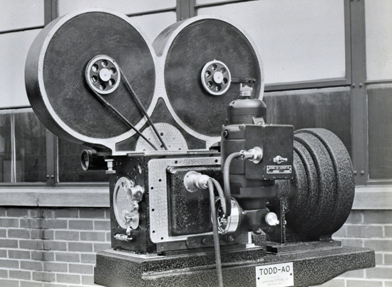 Rebuilt
Thomas Color Process 65mm camera, and renamed Todd-AO. Photographed outside
American Optical Research Center. Picture from Optical Heritage Museum. Rebuilt
Thomas Color Process 65mm camera, and renamed Todd-AO. Photographed outside
American Optical Research Center. Picture from Optical Heritage Museum.Now I must digress for a moment. Some 7 or 8 years before all this the Pullman Company had been forced by the U.S. Justice Department to divest itself of its railroad sleeping car business on anti trust grounds. They thus had a large amount of cash to invest and were looking at various options. One such was the invention of a man named Thomas that had developed a motion picture color process using additive color rather than the subtractive color of color films. He used a wide film with three black & white color separation red, blue and green images forming each frame of the film. When these were projected through suitable image combining prisms an additive color image appeared on the screen. Pullman asked my father (then at the Institute of Optics) to consult for them in evaluating the process. The upshot of it was that Pullman decided not to go into the motion picture business and the process was never heard from again. From Mike Todd we heard a rumor that somewhere in Hollywood there were some camera parts that had been used for a wide film process called Thomas Color. I immediately hopped a plane to Los Angeles and scouted around to see what I could find. Sure enough, in a warehouse was one complete camera and nearly complete sets of parts for six more, along with a nearly complete set of prints. I bought the whole bunch on the spot and had it shipped home to Southbridge by air express. These cameras were designed to house 65mm film with the standard Kodak perforations so we now had a film format that was just about what we wanted. Four times the area of image with the best type of perforations and a camera at least assembled. One problem remained with that camera. Thomas Color used an 8 hole pull down to get the double 35 images they needed, and we needed five holes for our format. We dumped the whole camera problem in the lap of our chief mechanical engineer, Henry Cole and enlisted the help of Mitchell Camera for camera construction. Henry and Mitchell did a very fast job of getting the first camera ready. Now we were on the way to having a workable camera we had to have film to run in it. With the pile of "junk" that I had picked up in Hollywood were some auxiliary pieces of equipment, like an old Bell & Howell perforator rebuilt for perforating 65mm film and an edge numbering machine. We sent the perforator back to Bell & Howell to be cleaned up and put in working order and then sent it to Kodak to perforate film for us (eventually they built their own because they had trouble making the old machine perforate to our tight specifications). |
|
IBM Card Programmed Calculator (CPC) |
|
|
In the meantime Hoppy was working on the camera optics. We arranged for a
teletype line from the A.O. computer room to his home near Rochester, New
York. The computer in those days was an IBM card Programmed Calculator
(CPC), but it was better than the hand punched Marchant desk calculators
that I tried to learn lens design on. Our lens design crew worked from the
Southbridge end with the computer and teletyped results to Hoppy who would
then make changes and the computer would go through another iteration. |
|
Distortion in Projecting |
|
 American
Optical engineers working on the Distortion Correcting Printing Process
printer. Picture from Optical Heritage Museum. American
Optical engineers working on the Distortion Correcting Printing Process
printer. Picture from Optical Heritage Museum.Another digression is in order at this point related to the basic geometry of the process. Cinerama had little distortion problem since they were projecting nearly perpendicular to each screen panel from those booths on the orchestra floor. We, however, are projecting from the normal projection booth onto an equally deeply curved screen. Thus at the edge of the screen the image is being projected from an angle to the surface of the screen. This presents two problems. First a horizontal elongation and second an illumination problem. The second I will cover when I discuss the screen technology, while the first is one of geometry. At this point we had to make a decision, namely at the edge of the screen was it more important to have people look right or to have buildings and nature to look right? The answer, of course, was that people and their faces were the more important. Thus it was important that a circle be reproduced properly everywhere on the screen. At the center of the screen a circle is reproduced as a circle, but at the edge a circle will be stretched horizontally. Therefore, on the film it is necessary that a circle at the edge of the field is horizontally compressed, and progressively less compressed as it moves to the center of the field. The correct law for this turns out to be that the compression should progress as the tangent of the angle moves off from the axis. Barrel distortion of a lens can be made to follow this law quite well. Since getting rid of all barrel distortion in a wide angle lens is very difficult anyway so our requirement was quite serendipitous. We now have produced circular faces all over the screen. However, buildings, trees, etc. at the edge of the screen will be bowed inward at top and bottom like a barrel stave (hence the term "barrel" distortion). This we called "Type A" distortion, and I will discuss it later when discussing the distortion correction printers. Remember that we are projecting from above the audience from the regular projection booth, so that we have two more distortions to consider for people seated below the line of projection. The "Keystone" distortion that is present in the conventional movie theatre is also present here. In addition since we are projecting from above onto a deeply curved screen, horizontal lines will appear bent upward at the edges to anyone seated below the axis of the projector. This we called "Type B" distortion or "Droop". |
|
Camera #1 Ready |
|
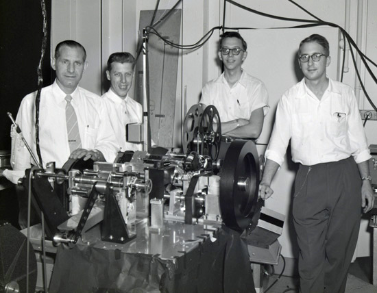
 Following
the prototype 65mm cameras from the Thomas Color Process, the Mitchell
Camera Company made brand new 65mm cameras for Todd-AO. Note the lamp house
on the floor to the right. Picture from Optical Heritage Museum. Following
the prototype 65mm cameras from the Thomas Color Process, the Mitchell
Camera Company made brand new 65mm cameras for Todd-AO. Note the lamp house
on the floor to the right. Picture from Optical Heritage Museum.Now back to camera optics. The "Bugeye" lens was being finished up and it produced the type of image described above. At the same time the number one camera was being finished, Kodak had produced 65mm Eastman Color negative, and first tests were started. After initial static tests Mike took the number one camera to the Far Rockaway roller coaster, the canals of Venice etc to produce a demonstration film to help convince Rodgers & Hammerstein and others of the power of the process. R&H had never before allowed any of their properties to be made into a movie, and they were dubious about Todd-AO. Mike Todd's "friends" and partners, namely George Skouras, Lee Schubert etc. were not in sympathy with Mike shooting a demonstration film, and moreover if Mike was out of the picture, there would be more gravy for them. So, while Mike was in Europe shooting they refused payment for more film from Kodak for him in an effort to shoot him down. Fortunately Mike was a survivor, and managed to eke out enough film to finish his shooting and this was the demo film shown in Amsterdam. I did not realize that a copy of it was still in existence. An interesting sidelight related to that film was a press showing of it at Stage 2 at MGM which was rigged as a review room for the process. At this showing the New York Times reviewer got so sea sick during the Venice sequence that he had to leave. We were sure that he would give it a bad review, but on the contrary he raved about the process. |
|
Screen |
|
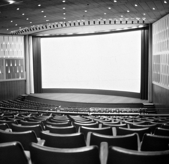 A
typical Todd-AO screen. Nearly 18 meters wide and deeply curved. Here the 3
Falke Bio in Copenhagen, opened October 1958. Picture by Thomas Hauerslev A
typical Todd-AO screen. Nearly 18 meters wide and deeply curved. Here the 3
Falke Bio in Copenhagen, opened October 1958. Picture by Thomas HauerslevWe will next take up the screen problems. If we project an image on to a deeply curved standard white diffusing screen, the scattered light from one edge of the screen will fall on the rest of the screen with the obvious result: light from a bright area on one side of the screen will wash out the dark areas on the other side. Cinerama had this problem, and their solution was to fabricate a screen of vertical strips of regular screen material, each one perpendicular to the incident light, like a Venetian blind. While this solved the spill light problem it was very fragile and expensive to produce. For the few Cinerama theaters it did not matter, but we were aiming for the general release theaters as well. What we wanted was a screen design that could be hung on a standard type of screen frame (although deeply curved), and also with as much reflective gain as possible to help produce the high brightness image we were after. This indicated an embossed lenticular aluminum type of screen material. The aluminized surface would not depolarize light in case polarized stereoscopic projection was ever wanted (remember, back then the stereo “3D” movies were fashionable.) What was needed was a material coated with a thermoplastic loaded with aluminum flake that could be embossed into small spherical mirrors. These spheres had to be oriented differently for different parts of the screen to prevent the cross-illumination problem mentioned earlier. The lines from the vertex of each sphere to its center for each lenticule ideally would be parallel and pointed out towards the audience. Obviously with lenticules of the order of 2 millimeters in size a compromise was needed. It turns out that five different orientations on either side of center was perfectly satisfactory in eliminating the cross illumination. The question was how to make the embossing rolls to produce this result? Swaging individual bumps on a steel roll was, obviously out of the question. We gave the problem to our chief metallurgist, George Granitsas and he came up with a very elegant solution. George had, over the years, developed processes for rolling patterns into the eye wires and temples of gold filled eyeglass frames, so he said “why not roll the spherical bumps on to one face of square wire and then wrap the wire on to a steel embossing drum?” We made up two steel embossing rolls, one with groove around it and the other with a raised portion around it that fit in the groove of the first one, but did not reach quite to the bottom. These were about 75mm in diameter. The bottom of the groove on the female roll was embossed with many spherical dimples around the roll, while the top of the raised portion of the male roll was smooth. If you now visualize these two rolls mated there will be a space between the groove and the “land” or raised portion of the other roll. If a ductile metal wire such as phosphor bronze is fed between these rotating rolls it will be swaged into square wire with spherical bumps on one side. This wire is now wound tightly around the full length of a steel drum about five feet long and one foot in diameter, and we have an embossing roll. Remember now we wanted the little spherical mirrors to be at different angles on different parts of the screen so they would essentially “point” at the audience, and not spread light over other areas of the screen. We figured that panels with five different angles would suffice. If the top of the land on the male roll is machined at an angle to the axis of the roll, the final wire will have a back that is tilted (and hence will no longer be square). By selecting five different angles we make embossing rolls with the bumps oriented at five different angles, and the problem is solved. My dad gave Ed Moon, one of our plastics and fabrication experts, the job of producing screens. After much experimentation, Ed came up with the proper formulation of vinyl coated cloth, and with a fabrication company to do the embossing, and they began to produce screens. With the flexibility that the above process gave us, Ed could build screens to fit any theatre on a custom basis. |
|
Film and Sound |
|
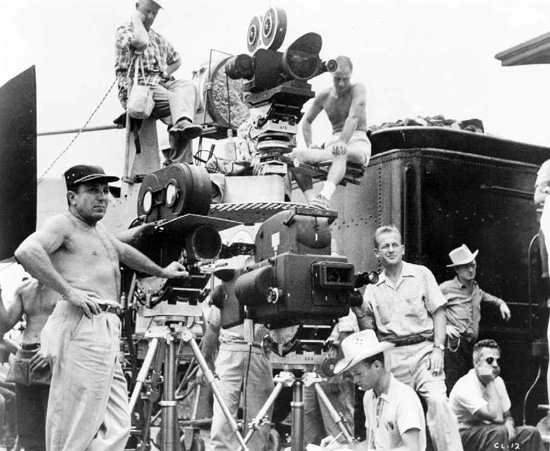 On
the set of "Oklahoma!" filmign in 65mm Todd-AO, and 35mm CinemaScope. Still
photo from "Oklahoma!" release, 1955. On
the set of "Oklahoma!" filmign in 65mm Todd-AO, and 35mm CinemaScope. Still
photo from "Oklahoma!" release, 1955.Now back to the film, and sound. We wanted to have nearly as possible true stereophonic sound. Now a slight digression for definitions. There are two methods of giving the observer the sensation of directionality in his perception of a sound - Stereophonic and Binaural reproduction. The simplest is binaural where each of the observers ears is presented with exactly what the ear would receive (in both amplitude and phase) if he were sitting at the original location (such as in a concert hall). This is done in practice by recording with two microphones placed like ears, and then reproducing this into earphones that must be worn by the listener. On the other hand, with stereophonic reproduction you do your best to reproduce the complete sound field in the theater that existed at the original location. This is normally done by multiple soundtracks and multiple speakers behind the screen and around the theater. For perfect reproduction an infinite number of both would be needed, but as a practical matter six sound tracks with three speakers behind the screen and three sets of surround speakers does an adequate job. In addition, there is a trick to enhance the sound localization effect. For a person sitting in the rear of the theater a sound coming from, say, the left screen speaker will not appear to be very far off center because of the small angle to the left. However, if that same sound then comes from the left surround speakers delayed in phase by a fraction of a second, the impression will be of that sound increased in amplitude and from way to the left. Because of this we wanted six soundtracks, three for the screen speakers and three for the three sets of surround speakers. The problem was that there was not room on the 65mm film. The solution was to go to 70mm film. However, it was extremely desirable to be able to run the camera film and print film on the same sprockets, so the extra 5mm was added outside the perforations and the soundtracks were placed out there. Magnetic sound recording had surpassed optical sound in quality, and the best was using the Minnesota Mining and Manufacturing Company’s (3M Co) so-called green oxide, which had the ferrite crystal all oriented so the noise level was much better than with the liquid applied striping on motion picture film. We initially went that route but there was one big problem. 3M (of all people!) had trouble with the adhesive used to laminate it to the film. The sound track would peel off on the projection room floor. Hence we ended up with liquid striping for our prints with two sound tracks outside the perforations and a third track was inside the perforations on each side. In those days, (and I presume still today) multitrack sound was recorded on 35mm magnetic film with standard 35mm perforations and this was run at standard motion picture speed of 96 perforations per second (24 four frames per second). We used a 5 hole pull down at 30 frames per second, and so our film moved at 150 perforations per second. Of course, this is the same ratio as 64 perforations (one foot) to 100 perforations (which we named the “gleep”). Since standard sound recording equipment was to be used, the editing “sync machines” had to be built with 65/70mm picture sprocket with a larger diameter than the sound film sprockets in the ratio of 100/64. We built a series of sync machines with one picture sprocket and from one to six sound film sprockets on the same shaft. |
|
Editing Machines |
|
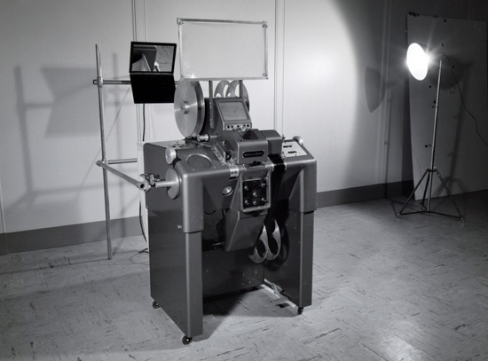 65mm/70mm
Editing equipment. Picture from Optical Heritage Museum. 65mm/70mm
Editing equipment. Picture from Optical Heritage Museum.Remember that this was the era when most editing was done on the old Moviola machines. The Westrex division of the Western Electric Co. had just recently introduced their new editor that used rotating prisms (glass cube) and continuously moving film instead of the intermittent sprocket pulldown of the Moviola. The Westrex machine was far superior, so we had them build them for our film. They couldn't handle the optics, so we provided the eight sided rotating prisms. In addition to a magnificent direct view of the film, we designed them so that the editor could project the image onto a curved screen so as to be able to better visualize the effect in a theater. Another modification was to have the sound film run at a different speed than the picture film i.e., one foot of sound film to one gleep of picture film so that they would stay in synchronism (the 64/100 ratio). |
|
Editing Accessories |
|
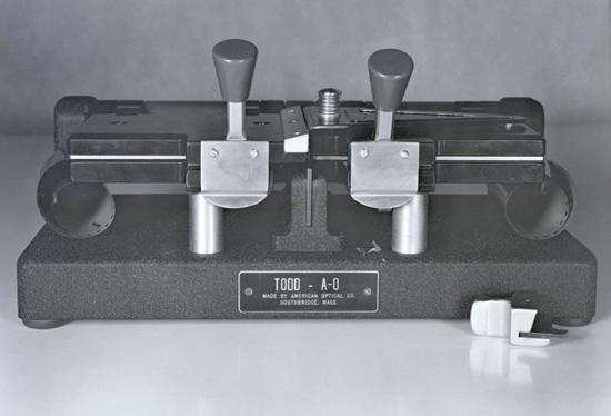 70mm
film splizer. Picture from Optical Heritage Museum. 70mm
film splizer. Picture from Optical Heritage Museum.All of the editing accessories, such as reels, hand rewinds, tight winds, of course had to be made to accommodate both 65mm and 70mm film. The editing reels had to be made for either 65 or 70, but the rewinds didn’t care and the weighted rollers on the tight winds for spooling film tightly onto core were machined with a smaller diameter, 65mm wide, portion inside the 70mm lands and flanges. Splicers had to be made for the film. We had Bell & Howell build a treadle splicer for us and we built a few hand splicers. |
|
Lenses |
|
 NEW
sight! NEW sound! NEW screen! NEW
sight! NEW sound! NEW screen!I have described the image characteristics of the wide angle or “Bugeye” lens earlier. The field of view was 132 degrees wide with the frame capturing 128 degrees. Because of the distortions described before, the lenses did not have a single focal length, but rather the focal length varied depending on the position in the field. Thus we designated the lenses by their angular coverage rather than the focal length designation of standard cine lenses. Initially we intended to have only the “Bug Eye” lens, analogous to Cinerama's equivalent of only one “lens”. However, the Hollywood types insisted that they must have a series of “longer focus” lenses for close-ups etc. We tried to explain to them that they would lose the audience participation effect if they went to narrower angles, but they insisted that they would only use them for close-ups. As a result we gave them 64, 48 and 32 degree lenses in addition to the 128 degree Bugeye. It was the biggest mistake we ever made!! These great “professional” cinematographers and directors didn’t have the faintest idea how to use the wide angle or participation effect, and so in the whole of “Oklahoma!” the Bugeye lens was used for two shots, the opening scene dollying through the corn, and one cut from the runaway buckboard carrying Laurie and Jud to the Claremore party. The rest was all shot with the narrow angle lenses. Mike [Todd] used the wide angle a bit more in “Around the World in 80 Days” but not a great deal more. |
|
The Corn in “Oklahoma!” |
|
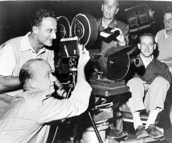 Head
Cinematographer Robert Surtees, adjusts the lens of Director Fred Zinneman's
16mm Eastman home movie camera on Arizona location. The big lens camera in
the center is the Todd-AO 65mm camera equipped with the 128 degree bug-eye
lens. Assistants watch during this rest between takes of “Oklahoma!” Head
Cinematographer Robert Surtees, adjusts the lens of Director Fred Zinneman's
16mm Eastman home movie camera on Arizona location. The big lens camera in
the center is the Todd-AO 65mm camera equipped with the 128 degree bug-eye
lens. Assistants watch during this rest between takes of “Oklahoma!”Some interesting sidelights on the corn in “Oklahoma!”. In the San Rafael valley south of Tucson, near the Mexican border where they built Aunt Eller's house, it was too cold and dry to grow corn very well. They hired a plant pathologist from the University of Arizona to try and do it. By starting it early and watering it daily from a tank truck driven up from Nogales, he was able to get a small corn field grown near the house. It was so short, that for shots of Father Carnes coming through the corn field, James Whitmore had to squat down to make the corn look tall enough! We estimated that the corn cost about $8.95 per ear. For the 19 second opening shot through the corn to a panoramic shot they had to inject each stalk of tall corn (corn never had been transplanted before), put it in a pot, and truck it up to the top of the hill to make a corn field just for that shot. The shots of Curly riding past corn singing “Oh What A Beautiful Morning” were all taken in the valley down near Tucson at some farmers stand of tall Mexican June corn. Finally they got corn “as high as an elephant’s eye”. |
|
| Go: back - top - back issues - news index Updated 21-01-24 |