
Cinemiracle.
Installation and Operating Procedures
| Read more at in70mm.com The 70mm Newsletter |
| Written by: R. H. McCullough. Prepared for in70mm.com by: Anders M. Olsson (Sweden). | Date: 16.10.2017 |
Foreword | |
 The
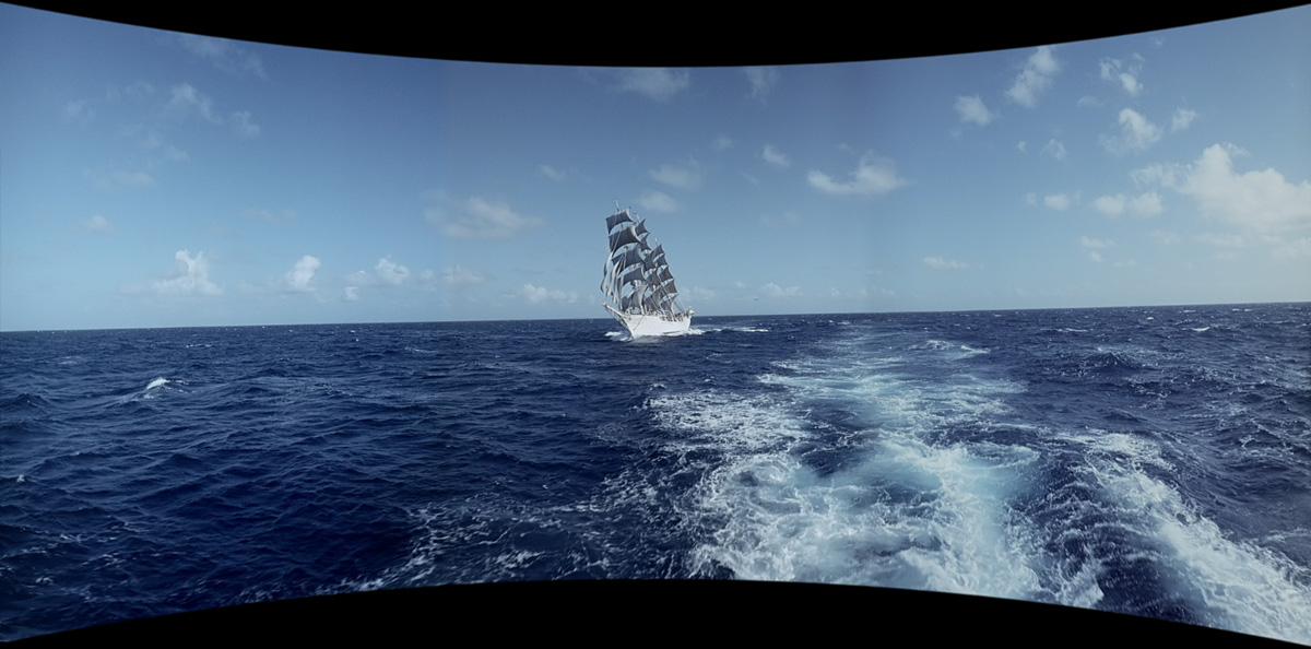
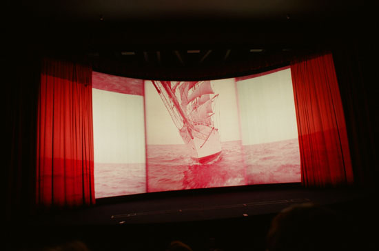
Christian Radich Mid-Atlantic
Under Sail. 2017 remastered version. Click to see enlargement. The
Christian Radich Mid-Atlantic
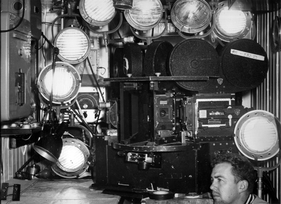
Under Sail. 2017 remastered version. Click to see enlargement.National Theatres Amusement Corporation's Cinemiracle is the newest of wide screen motion picture systems. The information in this booklet was prepared by Russell H. McCullough, director of research and in charge of this development. Cinemiracle uses a triple camera, using three 35 millimeter negatives. This results in the filming of a scene under a triple angle. Such a method gives, in principle, a vision in wide angle in the projection system, similar to that which one has in real life. Cinemiracle is a system of photography and projection developed by National Theatres Amusement Company and first used by Louis de Rochemont in the production of "Windjammer". This system uses a special three lens optical system, with a triple 35 millimeter Mitchell camera arrangement developed by the Smith-Dieterich Corporation, in which the use of mirrors makes it possible to bring the separate pupils of the lenses into optical coincidence, reducing parallax to a minimum. Electrical means are employed to insure utmost accuracy in image placement during focusing. In the theatre three projectors are electrically interlocked with a seven channel sound reproducer, in a single compact projection room at the rear of the auditorium. The projection angle is more or less level with the projection screen. |
More in 70mm reading: "Windjammer" in Cinemiracle Cinemiracle Operating Information for Handling Film Cinemiracle Projection Operating Procedure Sales Manual For Louis De Rochemont's Windjammer “WINDJAMMER” to set sail soon in a new digital version Internet link: |
 The
Christian Radich under sail. of the coast of Madeira. Dick Pietschman Collection The
Christian Radich under sail. of the coast of Madeira. Dick Pietschman Collection
Cinemiracle can be projected at any length of throw beyond seventy-five feet. The size of the picture is limited by the width and height of the auditorium. The center projector projects the center picture, while projectors #1 and #3 project the end images on the huge curved screen. Mirrors are used on the end projectors to extend the equivalent optical base line and to provide flexibility. The aperture of each side of the end projectors must overlap the sides of the center projector aperture to complete the Cinemiracle scene. The geometry of the system is designed to reduce distortion and shadow degradation most common in deeply curved screens, and to present a very nearly natural view to a greater portion of the audience. Vignetting of the overlap areas is accomplished in the printing stage with the use of a special printer head attachment. Dubray-Howell sprocket perforations are used throughout the process. The projection and sound reproducing equipment has been specially designed. Each projector mechanism includes a six-sprocket pull down intermittent movement. The Cinemiracle projection system has great flexibility as to the size and curvature of the projection screen. |
|
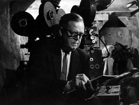 Louis
de Rochemont, Producer of "Windjammer" at the Mt. Eden studios. Note the
camera behind him. Dick Pietschman Collection Louis
de Rochemont, Producer of "Windjammer" at the Mt. Eden studios. Note the
camera behind him. Dick Pietschman Collection The specifications of the Cinemiracle system are as follows: Camera aperture - 1.110 inches (28.20 millimeters x 0.980 inches (24.8 millimeters). Projector aperture - 1.090 inches (27.70 millimeters x 0.960 inches (24.4 millimeters). Image height equivalent to six sprocket perforations. Aspect ratio of projected picture 2.33 to 1. Direction of film travel - down. Rate of projector film speed - 26 frames per second or 146.25 feet per minute. Sound film separate, full coated magnetic, synchronized with picture film, traveling at same rate of speed. Loud speakers - five behind screen, also distributed at sides and rear of auditorium. Screen - deep curve, constant radius, specially formulated, seamless, perforated plastic. The Cinemiracle prefabricated portable projection room is furnished by the E. F. Hauserman Company. Experienced craftsmen build the movable panels with special attention placed on their many construction features. All panel units are designed and built for fast erection and re-erection which can be handled by two men. The Hauserman Company have representation in sixty principal cities in the United States and can take care of our installation and removing the portable projection room, and packing and crating for the next destination. Sound transmission is reduced to a minimum with the use of incombustible rockwood insulation inside the metal panel partitions. The room interior wall and ceiling panels are perforated for additional sound absorption. |
|
Portable Projection Room
| |
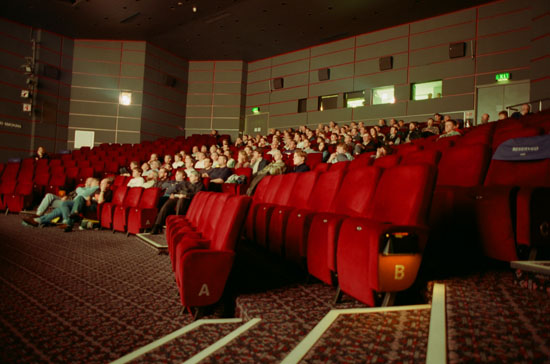
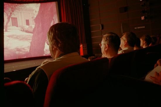 Audience
watching "Windjammer" in Pictureville cinema, 1997. The first public
presentation in Cinemiracle in 30+ years. Image: Thomas Hauerslev Audience
watching "Windjammer" in Pictureville cinema, 1997. The first public
presentation in Cinemiracle in 30+ years. Image: Thomas HauerslevPortable projection room size: 27 feet wide at front 24 feet wide at rear 16 feet deep 8 feet high Projection room should be more or less level with the center of the projection screen. Ventilation requirements: Fresh air inlet 12 inch by 12 inch opening in side wall of auditorium, or from other outside source. Duct will be flexible Thermaflex A. Projection room exhaust: 12 inch by 12 inch outlet to exterior. Duct will be flexible Thermaflex A. Projectors' lamphouse exhaust: 10 inch by 10 inch outlet to exterior. Duct will be flexible Thermaflex A. Inlet, projection room exhaust and projectors' lamphouse exhaust fans are located in the portable projection room. Where the exhaust ducts are extended to a long run, the lamphouse and the projection room exhaust fans will have to be placed at the end of the run. Electric service requirements: 200 ampere, 220 volt, 3 phase service for projector lamp rectifiers. It is desirable to locate the four rectifiers close to the projection room, otherwise an isolated location will suffice. Direct current wiring between rectifiers and projector lamphouse switches will have to be calculated according to length of run and amperage required for each projector arc, for size of projected picture, which will be unknown until survey is completed; 110-220 volt, 60 ampere service for projector motor drive equipment, dowsers, amplifiers, sound reproducer, rewind equipment, inlet and exhaust fans, projection room lighting, etc. This service is to extend from main distribution to portable projection room service switch. |
|
 Audience
watching "Windjammer" in Pictureville cinema, 1997. The first public
presentation in Cinemiracle in 30+ years. Image: Thomas Hauerslev Audience
watching "Windjammer" in Pictureville cinema, 1997. The first public
presentation in Cinemiracle in 30+ years. Image: Thomas HauerslevNote: Portable projection room includes all single phase internal wiring. Please provide length of run between main distribution point of single phase power to location of portable projection room, also the 3 phase run to rectifiers and direct current run from rectifiers to projector lamps. Total weight - 6 tons. Portable projection room - 7,000 pounds. Equipment in projection room - 5,000 pounds. In consideration of the fact that our Cinemiracle picture will have a height of 30 feet or more for large auditorium presentation, perhaps the portable projection room could be located in the balcony or mezzanine. During the preliminary survey it would be advisable to investigate if such a location could accept the weight of 12,000 pounds. Screen frame radius is shown on the enclosed drawing in accordance with the projected picture size and the length of throw. The width of the auditorium should first be considered and then refer to this drawing for the width of picture to meet the requirements. This drawing also includes the height of the projected picture. |
|
 "Windjammer"
in Pictureville cinema, 1997. The first public presentation in
Cinemiracle in 30+ years. Note the three panels are out of rack. This
was fixed by the projection team in a few seconds. Image: Thomas
Hauerslev "Windjammer"
in Pictureville cinema, 1997. The first public presentation in
Cinemiracle in 30+ years. Note the three panels are out of rack. This
was fixed by the projection team in a few seconds. Image: Thomas
HauerslevSix feet clearance is required behind the center of the projection screen for the center sound horn installation. The other four speakers behind the projection screen will follow the screen radius. For the average auditorium, six side wall and two rear wall speaker cabinets are used and are connected to the sixth and seventh channels of the sound reproducing system. The screen frame is free standing, with angle bracing at the rear. An acoustical blanket covers the entire back of the screen frame. A bracket arrangement is provided at the top front of the frame which supports the traveler curtain and masking border. This curtain is operated by a 3/4 horsepower, 3 phase, 220 volt motor, which includes a two-way stop position; one position is used for the prologue picture size and the other position for the Cinemiracle presentation. There is also provided a movable top masking border, operated by a 1/2 horsepower, 3 phase, 220 volt motor, which is dropped in position for the prologue picture and is raised during the Cine-miracle presentation. Three phase service is required at the location of the screen frame. Please give length of run for this service from main point of distribution to screen frame location. Keep in mind also to locate the control switches either on the stage or in the projection room for the front curtain. ACTUAL PICTURE SIZE SCREEN FRAME SIZE 30' x 70' 32' x 72' 35' x 80' 37' x 82' 38' x 90' 40' x 92' 43' x 100' 45' x 102' 47' x 110' 49' x 112' Aspect ratio of projected picture 2.33 to 1. |
|
Cinemiracle Projection Equipment | |
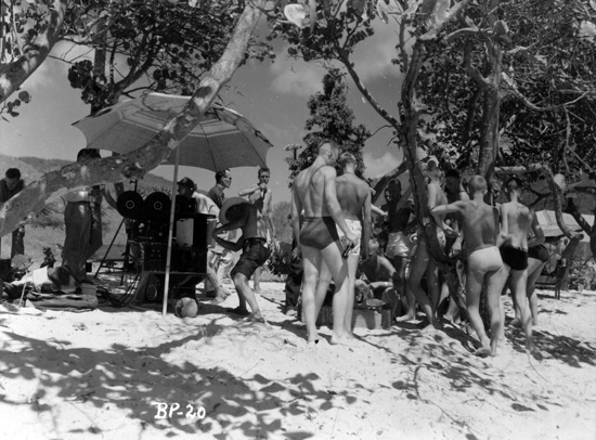
 Filming
beach party scenes in Cinemiracle. Dick Pietschman Collection Filming
beach party scenes in Cinemiracle. Dick Pietschman Collection 3 - Cinemiracle Century (Model G) projector mechanisms, complete with automatic dowsers, and water and air cooling, and a special lens jacket. 3 - Water circulators for projector mechanisms. 3 - Century Model C pedestals, with shifting devices. 3 Sets - Special custom 12,000 feet upper and lower magazines. Take-up magazines include torque motors. 3 - Motor mounting brackets, including Century Motor MO-21 110 volt, for 50 or 60 cycle operation, also flywheel and belts. 3 - 165 Ampere Cinex Ashcraft mirror projector lamps, with blowers and filters. Note: This type of lamp will be used on installations with screen sizes up to 100 feet in width, and above this screen size a larger capacity lamp will be used. A water cooling circulator is used for each projector lamp. 3 - F 1.9 Kollmorgen objective lenses. 3 - 12 Phase Ashcraft continuous duty selenium rectifiers, 90 to 180 amperes. 2 - Front surfaced mirrors for end projectors, with holders and adjustable mounts. Also remote control equipment for matching projected panels. |
|
 Filming
beach party scenes in Cinemiracle. Dick Pietschman Collection Filming
beach party scenes in Cinemiracle. Dick Pietschman Collection 9 - 10,500 Ft. Aluminum film reels. Note: The regular Cinemiracle performance will include six 8,000 feet reels of safety film. Three of these film reels are used during the first half of the presentation and the other three will be used for the last half. There will be a total of approximately 48,000 feet of film for the complete showing. Besides there will be 16,000 feet of magnetic sound tape split into two separate reels. Each theatre will be provided with a complete spare film print and sound film. Rewind equipment end tables, film storage cabinets, film splicer and synchronizer. 1 - Complete prologue 35 millimeter projector with mechanism, lamphouse, base, magazines, rectifier and lens, etc. Fire extinguishers, trash and carbon waste cans. Each theatre will have one complete spare Cinemiracle Century projector mechanism and two spare intermittent movements, and many other spare parts, for emergency use. |
|
Selsyn Interlock System | |
 Camera
crew Joe Brun, Bob Gaffney and Tom Conroy. Dick Pietschman Collection Camera
crew Joe Brun, Bob Gaffney and Tom Conroy. Dick Pietschman Collection
The projector installation includes three General Electric 110 volt, 60 cycle Selsyn interlock motors #2JA33BB1, which are interlocked with each projector motor. Another of the same type motor is interlocked with the 7-track sound reproducer. Primary voltage G.E. Selsyn motor #2JA33BB1, 110 volts, 60 cycles. Secondary voltage 55 volts. Plus or minus ten per cent on voltage variation rated volts per cycle. Plus or minus one per cent frequency allowance. The General Electric 110 volt, 60 cycle Selsyn motor #2JA33BB1 can also be operated on 50 cycles with the use of a General Electric auto transformer #9T5146171. The primary voltage for 50 cycle operation is 96 volts and the secondary voltage is 46 volts. |
|
Cinemiracle Sound Reproducing Equipment | |
 Cinemiracle
Camera in Christian Radich's radio room. Bob Gaffney to the right. Dick Pietschman Collection Cinemiracle
Camera in Christian Radich's radio room. Bob Gaffney to the right. Dick Pietschman Collection
1 - Stancil-Hoffman 7 channel sound reproducer rack, with seven preamplifiers and power supply, which accommodates two 8,000 feet magnetic tape reels. This reproducer is also equipped with a synchronous motor for individual operation, i.e., when the reproducer is not in interlock with the three projectors it can be run separately. 8 - 75 Watt RCA 12182 Type SA 75A power amplifiers. One of these amplifiers is used as a spare. Note: The output power will be increased if necessary for larger auditoriums. The power amplifier system is provided with an emergency switching system and in case one channel ceases to function it can be switched to another channel. This amplifier has been designed for reliable operation. Its exceptional frequency response and low distortion characteristics make it an ideal amplifier for high fidelity and wide range sound reproduction. The three Cinemiracle projectors facing the projection screen are defined as follows: "A" projector at right projects the left panel on the screen. "B" projector projects the center panel, and "C" projector at the left projects the right panel on the screen. The "B" projector includes a penthouse sound reproducer. The "B" film print includes two magnetic sound tracks, one at the outer edge of each of the sprocket perforations, which includes the complete film recording for emergency use. If for some reason the 7-sound track reproducer would cease to function, this emergency sound on the "B" film print could be switched in on the third and fourth power amplifier channels. All sound equipment is pin plug connected for portable use. 5 - RCA #PL301-A speakers are equally spaced behind the projection screen and they are mounted on steel towers. Each speaker includes: 2 - #MI 9595 Hi frequency horns 2 - #MI 9584A Hi frequency mechanisms 1 - #MI 9462 Low frequency baffle 2 - #MI 9449 Low frequency mechanisms 8 - Side and rear RCA Type LC-1A sound units with MI-11406 wall speaker cabinets. These speakers work in conjunction with the 7-sound track reproducer. The prologue projector is equipped with a penthouse magnetic sound reproducer. |
|
Procedure to remove either synchronous motor or interlock motor on Stancil-Hoffman D5A 7-Track Reproducer | |
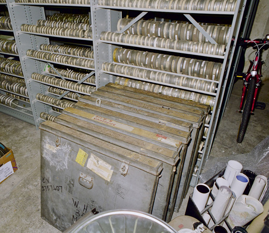 Transport
containers for "Windjammer". Six reels of film, and two reels of sound
in Pictureville's basement storage, 1999. Note the size, compared with
the bike. Image: Thomas Hauerslev Transport
containers for "Windjammer". Six reels of film, and two reels of sound
in Pictureville's basement storage, 1999. Note the size, compared with
the bike. Image: Thomas HauerslevBoth motors are mounted on an aluminum casting, which, in turn, is held to the vertical panel by means of two cap screws. One of the cap screws is mounted through a slot in this casting so that the chain may be tightened or loosened. Each motor shaft has fibre sprockets mounted which drive the chain and effect the gear reduction necessary. The synchronous motor operates at 1800 r.p.m. at 60 cycles (1500 r.p.m. at 50 cycles) and the interlock motor operates at 1560 r.p.m. at both 50 and 60 cycles. The synchronous motor is never to be operated while the interlock motor is energized. If this should happen, that both motors be energized at the same time, it could possibly strip the teeth of the fibre sprockets or at least loosen the sprockets on the shaft. To remove either of the motors, loosen the cap screws that hold the motor casting to the panel. Withdraw the motor sufficiently to remove the chains from the sprockets. If it is only desired to check the fibre sprockets or tighten them, it is not necessary to electrically disconnect the motors for this inspection. Naturally, if the motor is going to be completely replaced, the electrical connection will have to be removed. On the synchronous motor shaft is mounted a 26-tooth sprocket. This is lined up with and chain drives a 30-tooth sprocket on the interlock motor. The distance from the panel to the groove of these two sprockets is 1-3/4". Also mounted on the interlock motor is a 20-tooth sprocket which is chain coupled to the 80-tooth fibre sprockets. The distance from the panel to the center groove of the sprocket is 2-1/8". The gear ratios of this system are such that the synchronous motor, operating at 1800 r.p.m., drives the film sprocket at 390 r.p.m. and the interlock motor at 1560 r.p.m. drives the film sprocket at 390 r.p.m. When reinstalling the motors, it is best to leave about 1/4" slack in the chain rather than have it extremely taut. |
|
Projection Screen, Screen Frame And Draperies | |
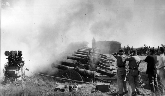 Filming
canons at Helsingør castle, Denmark. Dick Pietschman Collection Filming
canons at Helsingør castle, Denmark. Dick Pietschman Collection The screen frame is constructed of tubular steel and is flexible for the desired radius. A walk platform is installed near the top, at the rear of the screen frame, which eliminates the use of bulky towers for lacing the screen. The projection screen is masked with black velour. An acoustical blanket covers the complete rear area of the screen. The draperies include a front draw curtain, masking border and side legs, and a movable top masking border. The projection screen is perforated plastic and the surface is non-reflective. All draperies and the projection screen are fireproofed to comply with all Fire Department regulations. |
|
Cinemiracle Operation Information | |
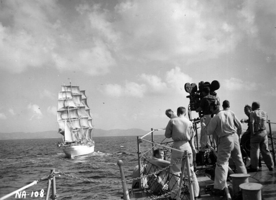
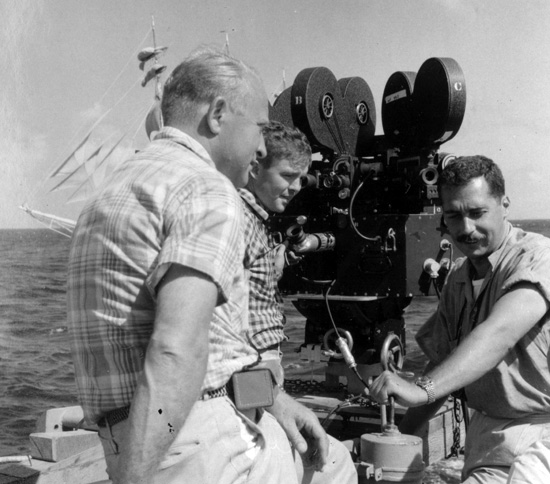
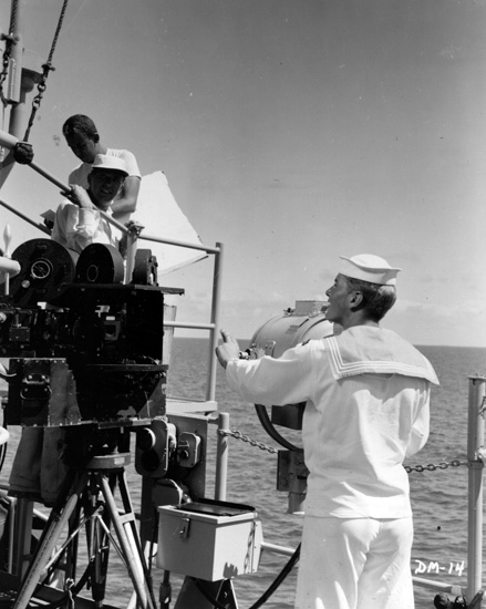 Filming
on board US Navy vessel. Dick Pietschman Collection Filming
on board US Navy vessel. Dick Pietschman CollectionThe three Cinemiracle projectors operate simultaneously with a 7-track sound reproducer and they are interlocked with single phase Selsyn motors. The main control for starting and stopping the projectors and sound reproducer is confined in a console at the right of projector "B". The control for the prologue projector and the changeover and switch controls for the sound equipment are also at this location. Each projector can be run individually when not in interlock position. The same applies to the sound reproducer. Automatic dowser control is installed on each Cinemiracle Century projector mechanism and is controlled at projector "B". At each projector a switch panel is provided for individual operation and this panel also includes the projector lamp rectifier control. A differential control is provided at the projector "B" switch. The sound reproducer is located at the rear in the main projection room, which includes seven preamplifiers and the preamp power supply. This sound reproducer is 24 3/4 inches wide, 17 inches from front to back, and 6 feet, 4 inches in height. The volume controls for the stage and auditorium speakers are operated from a control panel in the main projection room, on the front wall at the right of projector "B". The Cinemiracle projector mechanism is manufactured by the Century Projector Corporation. Specifications are as follows: 1. Special heavy duty intermittent movement. 2. 24-Tooth intermittent sprocket. 3. 24-Tooth feed and take-up sprockets. 4. Water cooled film trap. 5. Air cooled mechanism, which eliminates fifty percent of the heat emanating from the projector arc light source. 6. Right angle drive for framing, with frame indicator. 7. Right angle drive for focusing. 8. A stabilized lens mount to eliminate possible picture shift where focusing. 9. All light openings designed for 1.6 speed. 10. Automatic electrically controlled dowsers. 11. The interlock motor is directly coupled to the main drive shaft and runs at the same speed as the shutter shaft. 12. An indicator is provided on the operating side of the mechanism showing the shutter position, for interlocking and threading purposes. Film Magazines: The take-up magazines of the three projectors are equipped with Bodine 110 volt torque motors. When the master contactor is switched into the projector and reproducer motor circuit, a time delay enables the motors to start slowly, thus avoiding a quick start, which eliminates the possibility of breaking the film at the lower take-up sprocket. The Cinemiracle 12,000 foot film feed magazine, commonly known as the top magazine, is located at the left, alongside the take-up magazine. A film chute with guide rollers is employed between the feed magazine and the top of the projector mechanism. A sprocket is provided at the top of the film chute and the film is looped between this sprocket and the top feed sprocket of the Century mechanism. The feed magazine is equipped with a break clutch, which maintains an even pull. |
|
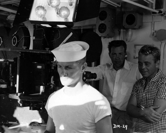 Filming
on board US Navy vessel. Louis de Rochemont III to the right. Dick Pietschman Collection. Filming
on board US Navy vessel. Louis de Rochemont III to the right. Dick Pietschman Collection.
Cinemiracle Pedestal: The projector pedestal used by Cinemiracle is a standard Century base, manufactured by the Century Projector Corporation, which includes a floor track for moving the complete projector forward or backward. Cinemiracle Projector Mirrors: There is a front surfaced mirror used in connection with the optical system on the two end projectors which are mounted on a special bracket arrangement. The mirror bracket is supported by a plate, which rides on two guides for moving the mirror forward or backward for picture size adjustment. When the correct position is attained, a lock screw holds the mirror firmly in place. Each of the end mirrors is remotely controlled to the projectionist's operating position, which includes a dial indicator. These mirrors are quite useful for blending the image match of the projected picture panels. A careful study of the three panel projection system for perfection, by our research department, has taken considerable time. Cinemiracle does not use any mechanical equipment on any of the three projectors for vignetting the blend line, where the three projected panels meet on the projection screen. The vignetting takes place in the printing process. National Theatres had a special printer designed and fabricated for this purpose. The vignetting is on the film and when the end projected panels meet the center projected panel, the blend line is suppressed and disappears. The vignetting is not critical in adjustment because a wide range has been allowed with plenty of tolerance. Care of Cinemiracle Mirrors: Front surfaced mirrors used on the two end projectors are delicate and easily damaged. They should never be touched or even wiped off with a soft cloth, however they can be dusted with a camel's hair brush using the brush very lightly. We have found, through experience, the best method for cleaning is to carefully remove the mirror from its holder and submerge it in a bath of distilled water with a few drops of Aerosol. After removing the mirror from this solution place it in a vertical position in a drain pan, and pour or spray fresh distilled water over the surface from the top, and let this water drain off until the mirror is completely dry. If this procedure is followed it will avoid water spots. If for any reason oil or any other substance should accidentally come in contact with the mirror surface, it can be removed with a piece of absorbent cotton moistened with denatured alcolhol. Cinemiracle front surfaced mirrors should last indefinitely with the proper care. |
|
Instructions For Operating The Precision Magnetic Film And Tape Sound Reader | |
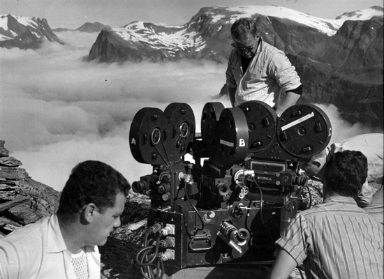
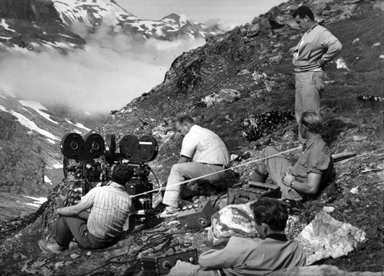 Filming
in Norway's mountains. Dick Pietschman Collection. Filming
in Norway's mountains. Dick Pietschman Collection. 1. To switch on the instrument turn the control knob, which is also the volume control, clockwise. 2. Pilot light (6 volt) on the front panel glows red, indicating that the amplifier is on. 3. To engage or disengage the magnetic head turn the knurled eccentric shaft clockwise until it snaps into position. 4. To adjust the magnetic head for track location, turn the knurled knob counter-clockwise to move and clockwise to move in. 5. The combination rollers are machined to give you 35 m.m., 17.5 m.m., 16 m.m. and 1/4 inch grooves, for magnetic film or tape. The combination rollers are shipped for use with 35 m.m. and 17.5 m.m. magnetic film. In order to adjust for a 16 m.m. size, collapse the roller to snap in next groove. 6. Fuse holder in the amplifier chassis is located in the rear of the instrument, and holds an AGC 1 - 1 ampere glass tube fuse. 7. Tube complement: 1 - 6AQ5 1 - 6C4 1 - 6x4 1 - 12AY7 Note: The phone jack on the speaker is used only with the precision magnetic sound reading attachment for synchronizers as an auxiliary amplifier. When attachment is not in use remove phone plug for regular operation. |
|
Electronic Component Part For Magnetic Sound Reader Model 700 | |
 Filming
in Norway's mountains. Dick Pietschman Collection. Filming
in Norway's mountains. Dick Pietschman Collection. C1 - .002 Mfd. 600 WVDC Tubular Condenser C2 - .002 Mfd. 600 WVDC Tubular Condenser C3 - .01 Mfd. 600 WVDC Disc Ceramic Condenser C4 - .006 Mfd. 600 WVDC Tubular Condenser C5 - 25 Mfd. 25V WVDC Electrolytic Can C6 - 10 Mfd. 450 WVDC Electrolytic Can C7 - 10 Mfd. 450 WVDC Electrolytic Can C8 - 20 Mfd. 450 WVDC Electrolytic Can CS - 20 Mfd. 450 WVDC Tubular Electrolytic Condenser R1 - 270K ½ Watt Resistor R2 - 100K ½ Watt Resistor R3 - 270K ½ Watt Resistor R4 - 100K ½ Watt Resistor R5 - 1 Meg. Switch and Volume Control R6 - 100K ½.Watt Resistor R7 - 2200 Ohm ½ Watt Resistor R8 - 470K ½ Watt Resistor R9 - 270 Ohm 1 Watt Resistor R10- 10K ½ Watt Resistor R11- 470 Ohm 1 Watt Resistor PL1- RCA Plug PL2- Amphenol Plug V1 - 6-8 Volt .15 Amp. Pilot Lamp #47 T1 - Power Transformer 325-0-325 RMS 40MA, DC 6.3 VCT 2 Amps |
|
| Go: back - top - back issues - news index Updated 22-01-25 |